Previous Work on a Helm: https://svseeker.com/helm.htm
www.edsonmarine.com
The information below came from Edson Marine regarding a helm system for Seeker. However the cost is thousands of dollars and I suspect we can do better building a comparable system from scratch. –Doug
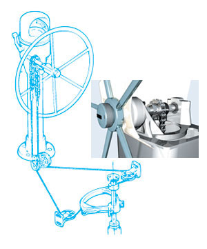
Edson: Calculations we have done. It was done with a 48” wheel and a 24” quadrant. We would need to use a geared steerer (2:1) in order to reduce the rim loads to an acceptable level. We recommend that the autopilot, typically an hydraulic actuator, would be attached to a tiller arm on the rudder shaft. This provides complete redundancy, the autopilot and the mechanical system. We do not have a quadrant or tiller arm that is off the shelf for a 10.75” shaft. These would be custom fabrications. The reduction gears are spur gears and can be back driven by the autopilot. There is no shear pin or weak link. We do not want the system to fail. Probably the worst load that you can put into the system is if you lose control of the wheel when backing up. The rudder slams against the stop with the full inertia of the wheel and the force of the water.
Edson Quote for helm parts not including the quadrant:
Here is a preliminary quote for the steerer, wheel, sheaves, and chain and wire kit. I do not know your layout so I made some guesses on the number of sheaves and the length of the wire. You will need to make sure you have adequate space for the chain to travel to the first sheaves. It should be about four feet depending on the travel of your rudder. Not knowing where you plan on running the wire I included six sheaves but often you can do it with four. The wire we use is steering cable which is the strongest non magnetic cable available and is pre-stretched for precise steering. Let me know what you think and I can fine tune the equipment for your application.
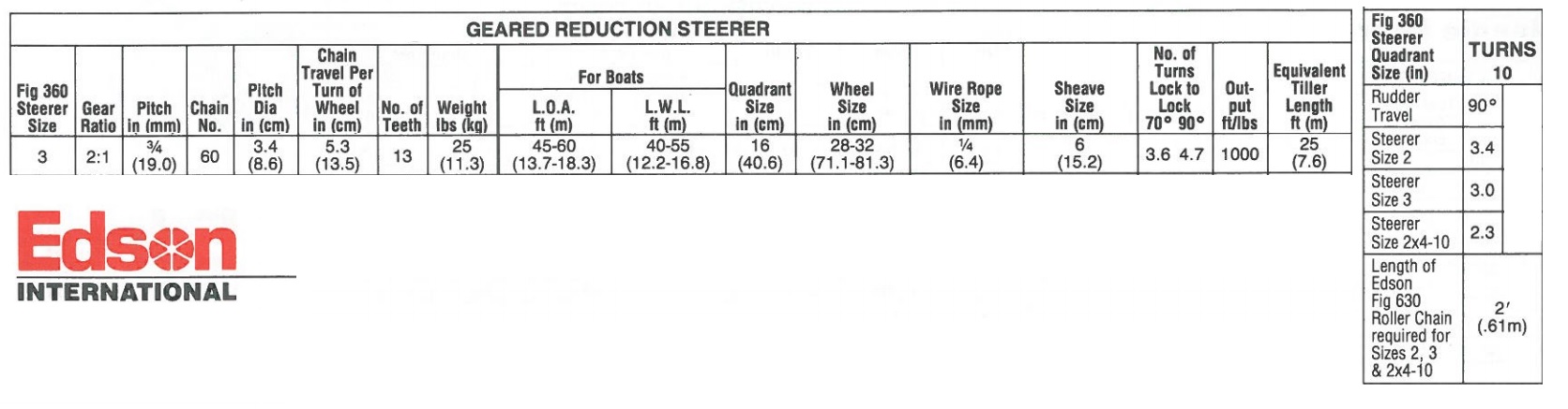
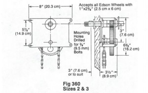
Information on the geared steerer is attached. We would recommend the 360-3-10.
Possible Suppliers
Hub City http://www.hubcityinc.com/
Surplus Center https://www.surpluscenter.com/
Boston Gear http://www.bostongear.com
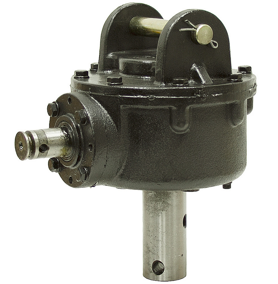
Bush Hog Gearbox / Post Hole Augger
I just lov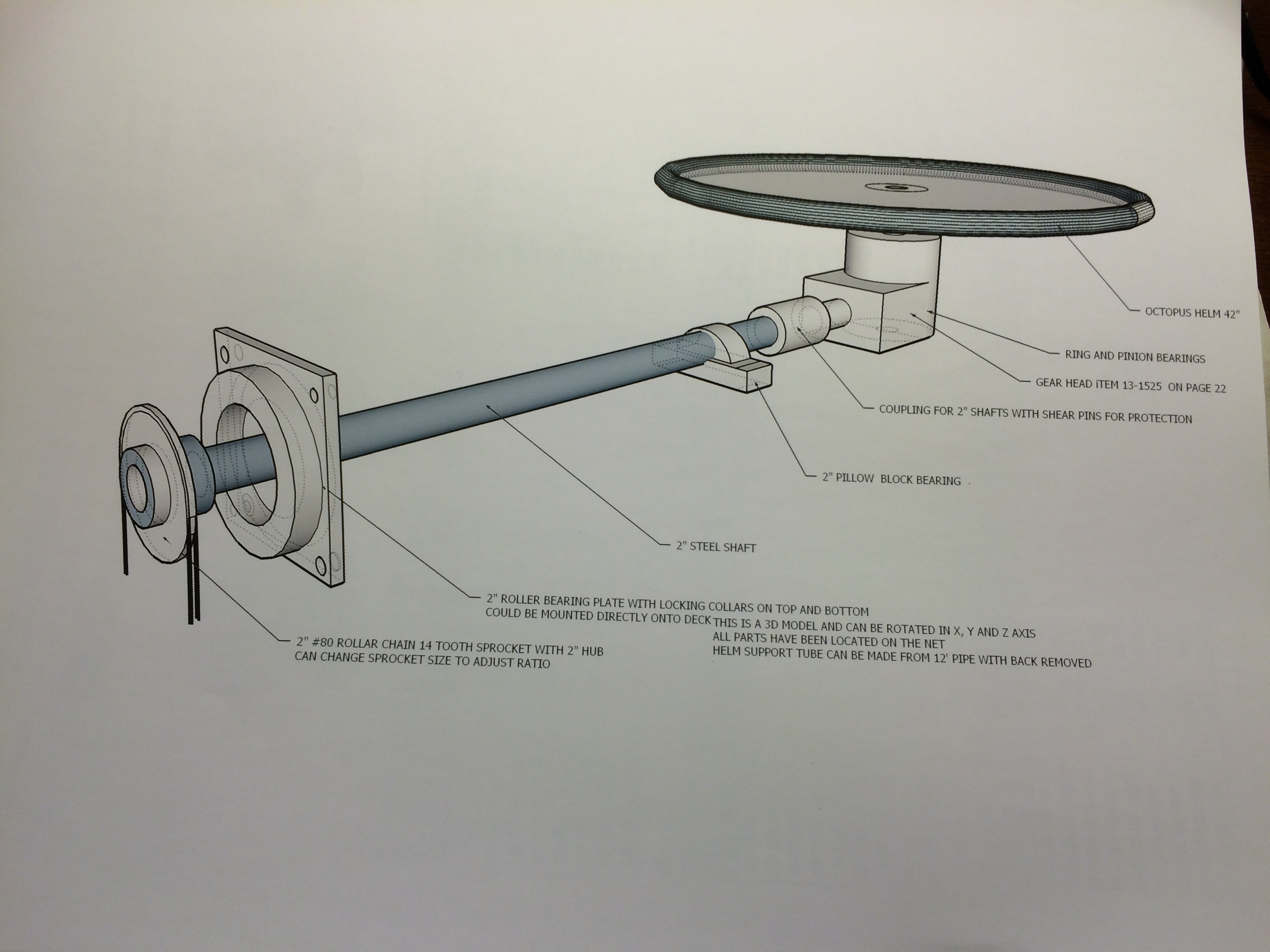 e this idea from Bill Pearson. I spent a lot of time with one of these whirling behind me and the Massey Ferguson. It has a sealed oil filled gear box that should last a lifetime on a boat. Tractor power takeoff runs around 540 rpm so this reduces the out put. Three turns in gives one out. It is the same as bush hog post hole digger. I went to a tractor dealer this morning to ck one out up close. Very little back lash and can turn the out put and make the input turn. That’s important for feeling the drag on the rudder from not having sails balanced. (How u balance the sails). Bush hog gear box is $125 from the tractor dealer.
Post Hole Digger Gear Box $165 2.92:1 reduction ratio
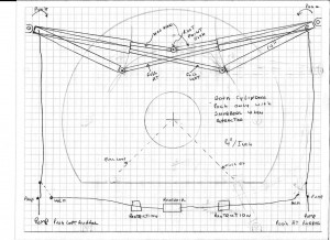
If we used the 24 in radius quadrant as specified by Edson, we would have to incorporate pulleys so that the quadrant protruded forward on the rudder post as displayed in the Edson helm illustration above. But if the quadrant was shortened to 15.5 in radius it could be shaped like a bow tie and turn 45 degrees without hitting the transom, and it would eliminate the need for pulleys. Fewer parts is always good in my book.
And no, I am not good a math. I have friends like Johan Storbjörk in Sweden. 🙂
So if the diameter of the quadrant radius is 15.5 inches. And the rudder is to rotate 90 degrees. And the wheel should turn 10 times from lock to lock. What is the diameter of the sprocket that goes on the bottom of shaft?
The radius of the quadrant is 15.5 inches, so the diameter is 31 in. And 31 times pi (3.14) gives 97.4 inches circumference.
We need to turn the rudder 90 degrees or 1/4 of a circle so the travel along the outer edge of the quadrant is 1/4 of the 97.4 circumference is 24.35 inches arc length.
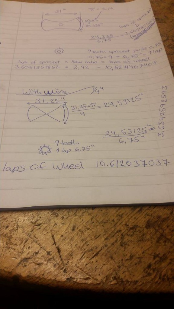
We want 10 turns to move the rudder 90 degrees. The ratio in the gear box is 2.92:1 so if we rotate that 10 times we get an output of (10/2.92)= 3.42 turns. 24.35 / 3.42 = 7.12 inches of travel per rotation or 7.12 inches circumference. The pitch diameter is 7.12 / pi (3.14) = 2.26 inches. A chart with the pitch diameter of #60 sprockets shows that a 9 tooth sprocket has a pitch diameter of 2.193.
Now we can work it out with a 9 tooth #60 sprocket. If the radius of the quadrant is 15.5 in., the diameter is 31 in. And 31 times pi (3.14) gives 97.34 in circumference. A 45 degree rotation of the rudder is a quarter turn. 1/4 of 97.34 is 24.3 in of travel. 24.3 / .75 for each tooth on the sprocket is 32.4 teeth. 32.4 / 9 teeth is 3.6 turns. 3.6 * 2.92 reduction ration is 10.5 turns of the helm.
Keyed sprockets Bore Size 5/8 to 1 inch Keyed Shaft Keyed Shaft Coupler & Flange Bearing $90
3/8″ Galvanized Steel Cable, Turnbuckles, Thimbles, and Cable Clips $200
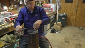
Tapping the Rudder Post
We attached the quadrant to the rudder post with 16 – 3/8″ bolts. But Darin, one of our online machinist observers gave us a the great suggestion of adding dowel pins. These will act the same as keys and help take the sheer force. He also suggest a center pin to take bending loads best explained that if a sheer pin on one side takes load it transfers load to the other side, like the center of a teeter-totter. So if we put a big pin in the center we load that, instead of the pin on the other side. 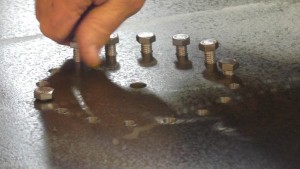 Darin explains it like this “… try putting your hands together palm to palm,then interlock your fingers and try rotating your hands against each other. What you will see is your fingers (the bolts) wanting to bend sideways and your palms wanting to shift off axis.” So a big pin where your palms are takes load from the bolts.
An alternative to a pin in the center is a ring on the bottom of the quadrant that slips down over the rudder post. We can make the ring, but we can’t turn the post on our lathe so the clearance could be rather sloppy. Instead I think we’ll go with 6 – 5/8″ pins. Those will easily take 10 tons each.
 Dave and others suggested we may be able to use the hydraulic pistons to not only move the rudder with hydraulics but also serve and hard point that slow the rudder’s movement at the end of it’s desired travel and then stop it from moving further.
“I know that you can buy cylinders that have snubbers in their retracted position, I think they are referred to as bumpers maybe. If you used the cylinders as snubbers when using the helm and hooked the cylinders up to a reservoir with a restriction in the return lines you could possibly eliminate the hard stops. In the case of a sudden impact on the rudder the hydraulic cylinders would slow down the movement and provide a hard stop. The restrictions in the lines would not effect the helm steering as you can’t turn it nearly as fast as a rudder impact. Please see the poorly drawn diagram and even more poorly copied idea that I have in mind. A picture is worth a thousand words, ok maybe this one has a value of less than that. One of your mechanical engineers could help with the geometries and sizing’s of the cylinders.” –Dave
The only problem I see is that in order to absorb 20 tons of force on a piston without greatly exceeding 3000 psi would require a cylinder that is 4 inches in diameter. (20*2000)/(pi*(2^2))=3183 psi. A margin of safety could be added by configuring the cylinder to cushion in both directions. But 4″ is still a really big cylinder. Maybe the key is just adding a relief valve that keeps the pressure under 3000 psi and allows the cylinder to bottom out. And have a cylinder that can bottom out and that can easily sustain more than 20 tons.

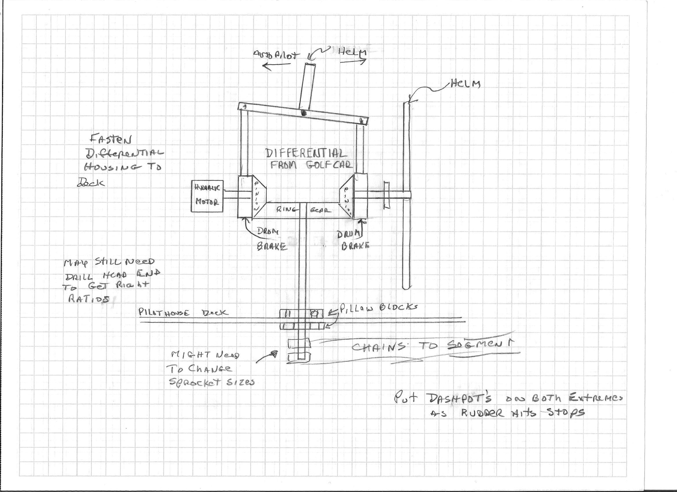
Helm Differential
Dave had another idea the involved using an golf cart differential. It’s considerably larger and heavier than the post hole auger, so we are not going to use it, but it’s still an interesting idea. The idea is that you can use brakes to select if the hydraulic motor of the auto pilot or if the wheel is steering the boat. I actually prefer to see the wheel move as the autopilot makes changes and I think removing the auto pilot from the system if needed is as easy as opening a bypass valve, or at worst, disconnecting the chain between the motor and the vertical drive shaft. However I actually prefer the auto pilot system to use hydraulic pistons as it is completely redundant to the chain and cable system.
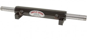
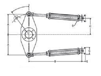
So back to the hydraulic cylinders. A single power steering cylinder, or double acting, or balanced cylinder is often used on boats. These cylinders require the same amount of fluid to push them in either direction. That means that hydraulic helms work to turn the rudder at the same speed in both directions.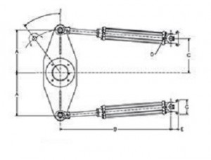
The same trick can be achieved by using two of the more common double acting cylinders. The cylinders are connect together so that as one extends the other is retracting. In that way the same amount of fluid is needed to move the rudder in both directions, so it moves at the same speed in both directions. I prefer the twin cylinder setup as it only has one additional hose, yet if one cylinder should fail it is possible to remove it from the system and still have rudder control, even if it does move faster in one direction than the other. It also allows both cylinders to share the load.
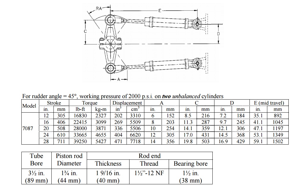
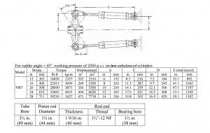 Borrowing from Kobelt’s literature we find an example for a system that with a 3 1/2″ Bore 1 3/4″ Rod, 20″ Stroke Cylinder can support 28,000 ft pounds, on a rudder that swings 45 degrees. The chart provides us the answers about where to mount the cylinder to the quadrant and that is 14.1 inches from the center.
SurplusCenter.com has 3.5 x 20 x 1.75 cylinders for $235 each. These are also available on eBay from Magister Hydraulics.
The volume for this cylinder totals about 1.5 gallons. That is the piston side and the rod side combined as two cylinders will be used. So a 12v DC hydraulic power unit typically delivers 1.3 to 1.7 gpm, so the full 90 degree swing of the rudder will take about 60 seconds.
The Wheel
David Collins came up with the design below. The plan is to use some thin wall 1-5/8″ OD stainless pipe that can be rolled into the outside wheel with an OD of 48 inches. And then some 1-1/8″ OD stainless pipe that we can use for the spokes. A removable adapter will be make for the input shaft on the post hole digger gear box and the other end of the adapter will be an 8″ diameter, 3/16″ thick steel plate.