
Rudder Steering Gearbox
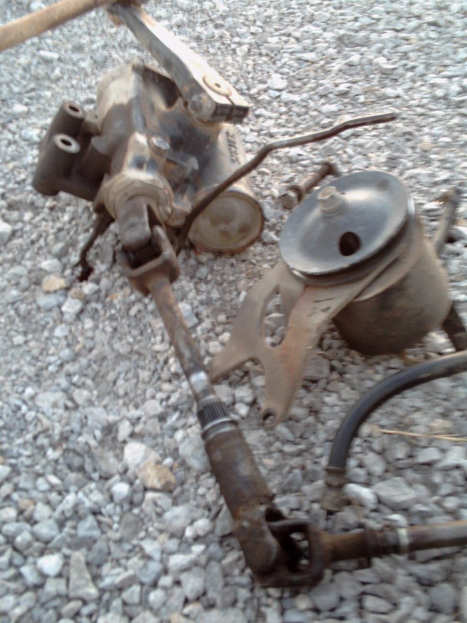
Steering gear box, drive shaft, and steering buster pump salvaged from a school bus.
If you get at all nervous about boat building decisions then looking at rudders will likely make your head explode. The real killer is they are not like anchors. You can trade this part out easily. My only advice is keep in mind how you are going to use your boat.
For us, Seeker is a work boat. Towing, hauling cargo, maneuverability, and ruggedness are top of the list. Meaning that speed under sail is going to take a hit.
www.rudderpower.com
www.rudderpower..com
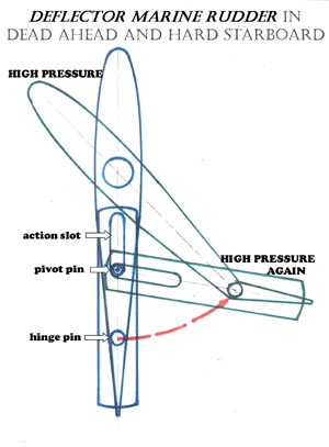
One answer to tight turns is the articulating rudder. The make for impressive turns but the down side is the additional moving parts and the maintenance that come with that. Their other down side is that they work very poorly in reverse.
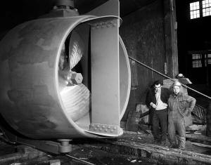
Kort Nozzle
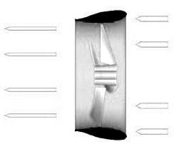
Rice Nozzle
The next big idea was a Kort nozzle. That idea quickly was put aside because we’re building a sailboat, not a tug boat. …but it kept coming back. Generally if you have never seen someone else do it then it’s a bad idea, but this one persisted. But not as a Kort Nozzle or a Rich Nozzle but as a simple propeller shroud. Kort and Rice Nozzles have flared openings so my thought is that they will have considerable more drag than just a shroud which is nothing more than a pipe.
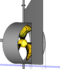
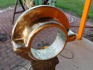
Fixed Propeller Shroud
On second thought, we decided we wanted the propeller shroud fixed to the skeg and a Fish Tail rudder foil trailing behind. The idea is to increase the reliability. The shroud to blade tip clearance is only 3/16″. If the cup bearing beneath the rudder were to wear just 3/16″ then the blades would have started striking the shroud. With them separate if we have damage to the shroud, we can cut it way, replace or repair the blades if needed and be on our way. If it’s par of the rudder, we be left with a very weak rudder once the shroud was removed. The dead wood or shoe extended out under the rudder is being debated. If it takes a hard it, it will bend and jam the rudder, but then it might save the rudder’s ass too.
Active Rudder
One other option, just because it’s so unique, is the “active rudder”. A hydraulic motor, controllable pitch propeller and Kort nozzle are build into the rudder which can swing 65 degrees to both sides giving the vessel great maneuverability and station keeping ability.
This example is on the Canadian Cost Guard vessel – TANU
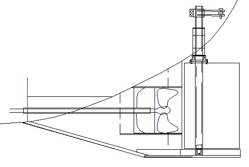
Fishtail Rudder
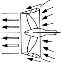
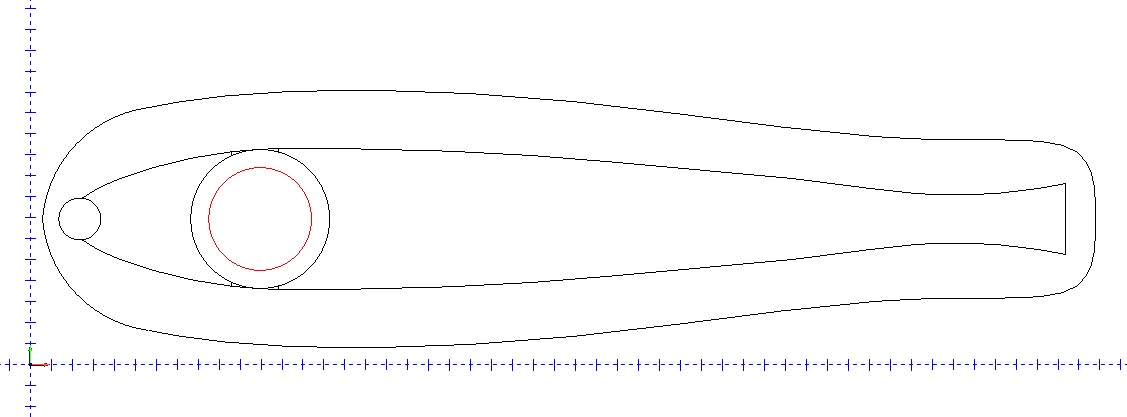 We selected to use a “fishtail rudder” straight out of Dave Gerr’s Boat Mechanical Systems Handbook. There are two advantages we like about the design. First is maneuverability. Most rudders, stall and become useless once they are turned more than 33 degrees to either side. But the fishtail rudder can be turned 45 degrees before it stalls. Secondly, as a workboat we run the risk of bumping into things like a rocks. The large forward width of the fishtail rudder allows us to use a very strong 6 inch diameter XXHW rudder post. While we may damage the rudder’s surface, we will not likely harm the rudder post which will make repairs much easier.
Specs: Rudder Tube: 10.75″ OD x 0.5 Wall Rudder Post: 6″ XXH 6.625OD, 4.897ID, .864Wall XXHY 53.21 llbs/ft
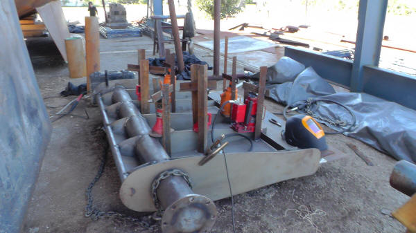
Using jacks to pull 3/16″ steel skin to the frames of the fishtail rudder
Rudder Collar
Mermaid pad eye
We cast a rudder collar that clamps to the rudder post and seats against the rudder tube mounted into hull, preventing the rudder from being pushed up into the hull. When the rudder need to be removed the collar is first removed, then the flange bolts are removed and the rudder raised up 4 inches until the pintle clears the rudder cup and the rudder is shifted sideways, clear of the cup.
The three, 3/8″ thick pad eyes on the transom and two on the top plate of the rudder allow for the 1000 pound rudder to be easily managed with 3 leaver chain hoist. When in the water the hollow rudder displaces 600 pounds dropping its weight to 400 pounds.
The void inside the rudder is air tight so no rusting of the inside will stop once the available oxygen is depleted.
www.edsonmarine.com
Steering Systems
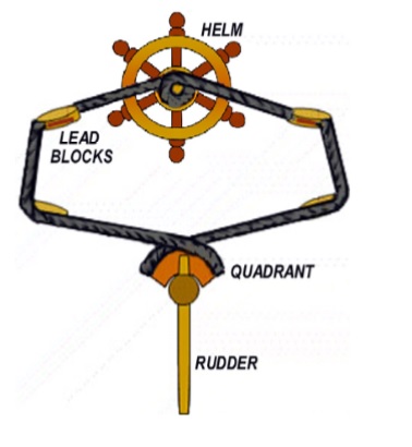
Chain and Cable
The old school approach of chain an cable is an interesting approach, because the parts can be built from scratch. The down side is routing the cables, but in our case that will be easy to do. And any power assist or autopilot system will have to actually turn the helm wheel. But while that is a little dangerous, it is a great visual feed back for the auto pilot.
We got a spec of a chain and cable system from Edson Marine. Edson_Marine_Helm_Specification It calls for a 2:1 reduction gear on a 48″ helm with 9.9 turns for a 90 degree swing. The sprocket diameter is 2.43″ and the quadrant radius is 24″. And the force on the wheel is 33 pounds cursing and 44 pounds surfing.
The Edson_Chain_and_Wire_Steering_Systems and Edson_Chain_and_Wire_Grear_Reduction documents contain information to design your own system.
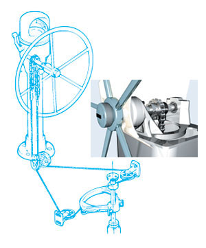
Hydraulics
Below is a typical setup for a hydraulic helm pump, however these pumps are very expensive for the size we require. For example a Kobelt Helm Pump, Model 7012 Variable Displacement 4 – 12 cu . in 1000 psi is over $2000. Hence, we’ve decided to use the chain and cable system described above. However we’ll also have hydraulic cylinders to drive the rudder which allow for control by an autopilot as also as a redundancy to the chain and cable system. The hydraulic cylinders are actuated by simple and relatively inexpensive electric hydraulic valves.
Balanced vs Unbalanced Cylinders: Most hydraulics for rudders use balanced cylinders, where the rod protrudes through the backend of the cylinder so that the same amount of fluid is needed to push the rudder in both directions.
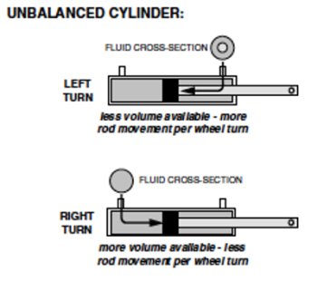
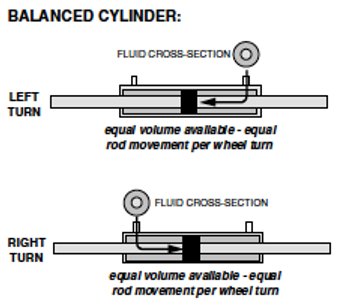
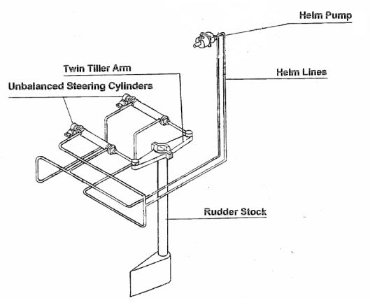
Unbalanced Cylinders used in a pair will balance the steering.
But unbalanced cylinders are more common and if you simply use two unbalanced cylinders you get the same effect and you can plumb around one failed cylinder and still have use of your hydraulic steering.
The rudder is designed to take over 21,000 foot pounds.
Auto Pilot
Hydraulic cylinders are welded, double acting, 3.5″ bore, 20″ stroke, 1.75″ rod, clevis, 30.25″ retracted, 50.25 extended, SAE 8 port, 28,800 lb column load. pi * (3.5/2)^2 * 20 * 2 = 385 cu in. The 10 gallon accumulator can provide 2 gallons ( 462 cubic inches) of at or above 1500 psi. That is more that sufficient to swing the rudder from stop to stop. The two 24v DC Direct Drive Pumps, output: 2.5 gpm at 1049 psi, max 2500 psi. Together they provide 5 gpm, 1155 cubic inches. 1155/385=3, so they can swing the rudder 90 degrees 3 times per minute, or once every 20 seconds once the accumulator is exhausted.
Various Rudder Area Size Calculations
A rudder area of between 8 and 10 per cent of the total lateral plane or underwater profile is the desirable size for a sailboat. Seeker is about 304 sq feet * .08 = 24.6 sq ft Down to 6% will do for rudders with high aspect ratios. (Tall)
With a skeg in front of a rudder, up to 12% of the rudder can be considered to be on the skeg. Unless the skeg is 80% of the rudder area and then it no longer counts because it acts more like a long keel.
The submerged portion of the rudder is typically 1% to as much as 2% of the sail area.
Seeker has 2196 sq ft of sail, which would be 22 to 44 sq ft of rudder. Seeker’s rudder is 20 sq ft.
Displacement Boat Rudder Area = .03 to .04 * Waterline Length * Draft Including Keel: Seeker is 12 to 16
Traditional Full Long Keel = .068 * Waterline Length * Draft Including Keel: Seeker: 26.52