
Modifying a Winch Truck Winch
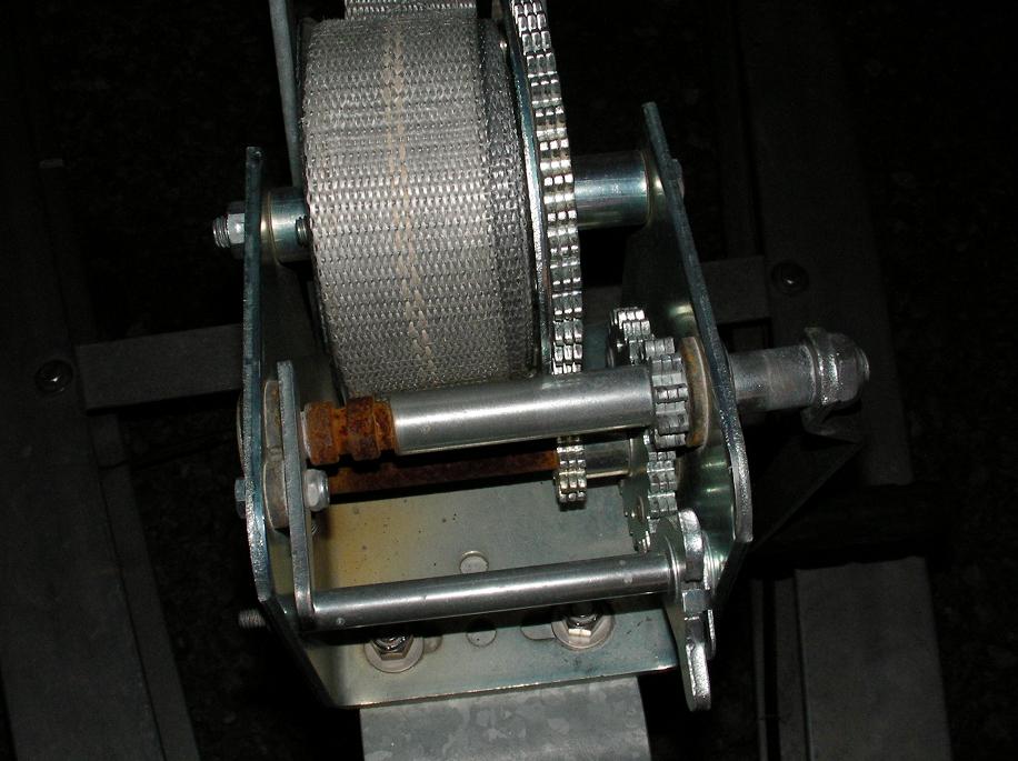
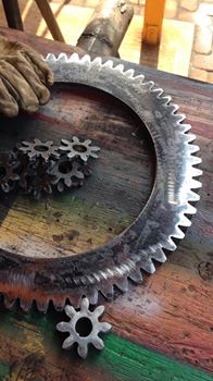
While pondering casting and cutting a lot of parts to build our own winch, we came across an old 1950’s “White” truck winch in the 15 to 20 ton range for $600. We looked at a couple of others but this one was not frozen up, moved smoothly and had recently been in operation. But it was seriously ugly and beat up. An two great things about this winch was that it is it has a dog clutch that lets the spool free wheel. A brake on the spool so the spool and any load it has can be locked, and then the dog clutch can be disengaged and the winch motor can then power capstans added to the ends of the drive shaft. And finally it is a worm drive winch with a 29:1 reduction and worm drives by their design lock the load in place. So when the motor stops the spool will not move even when it is loaded. The down side is that the brake, capstans, and clutch control arm are all missing. And the brake collar that is the surface used by the band brake was badly bent from years a abuse. So the first order of business was to rebuild the brake surface.
MIG Brazing
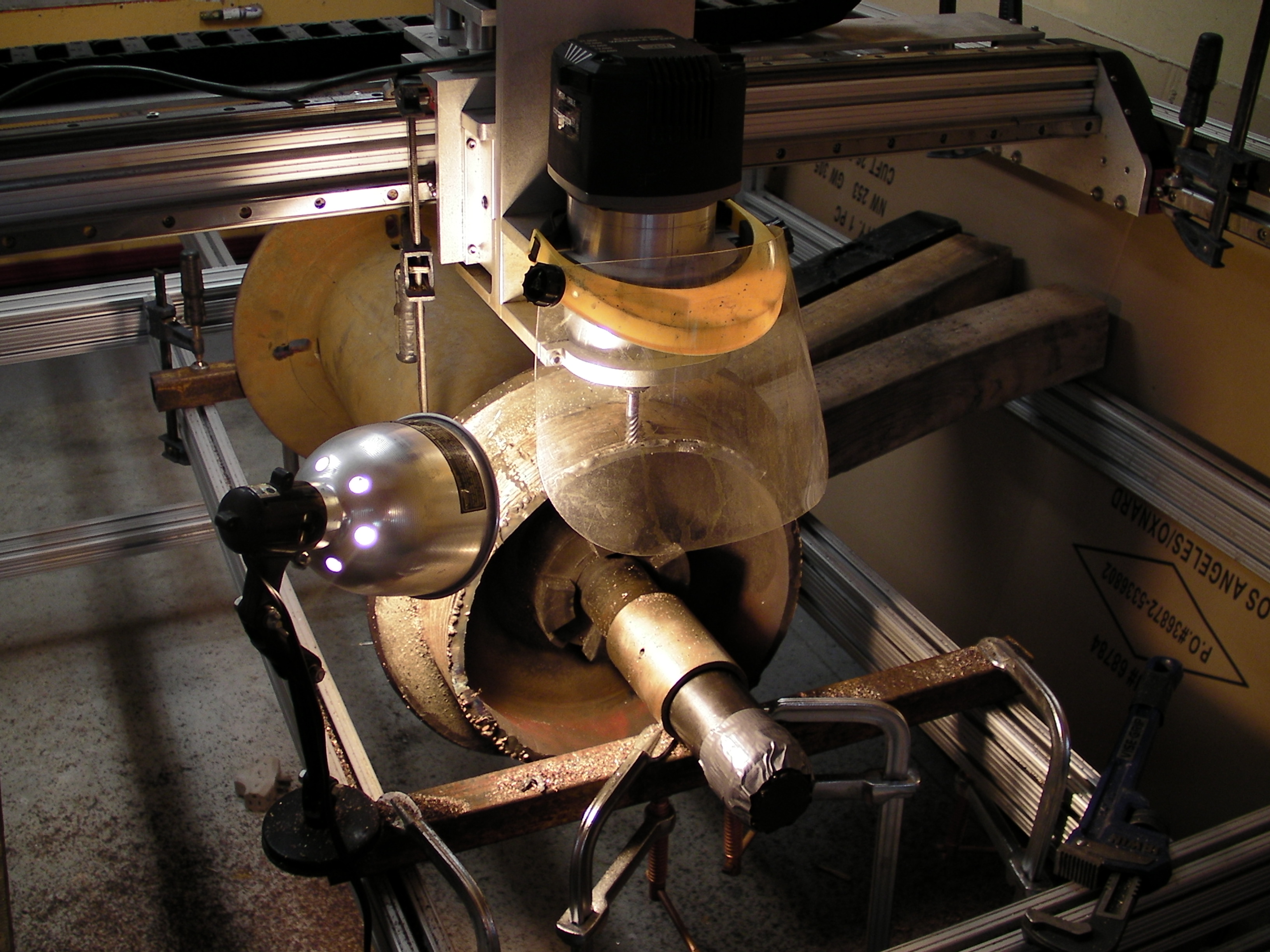
MIG Brazing the brake surface,
then cutting it round again, and
repeat until the surface is uniform
MIG Brazing is not a common process as most people have oxygen acetylene torches so they learn traditional brazing. But I got a crash course in MIG Brazing from a technician at our local AirGas welding supply store and it’s a great way to go if you already have a MIG welder.
Silicon Bronze wire will cost you around $10 a pound. We use .035 and .045 with 100% Argon cover gas. Argon/He is recommended but 100% Argon works fine. It’s a stiff smooth, wire so it has no problems feeding through the same umbilical and gun you use for steel wire.
Getting the settings right on our Hobart Iroman 210 was a breeze. Just turn the heat down. Keep in mind that you are brazing, not welding. The wire is going to melt and spread across the surface and pile up. It’s not going to dig into the base metal like welding. Getting our Lincoln Invertec power supply and Miller X-Treme suitcase welder to work took a lot of fiddling. For .045 Silicon Bronze wire the settings that worked were to switch the suitcase to “Soft Start” and 195 inches per minute feed and set the Lincoln to GMAW at 200 amps CC with positive to the wire. Preheating the parts is recommended but I and others have skipped the pre-heat with no short term problem.
Woodruff Keys
The drive shaft uses woodruff keys. But really big woodruff keys. That turn out to be a good thing because I discovered that I can cut large keys slots with a grinder and the keys are not difficult to make with a lathe and a few other tools. A mill would do a better job of cutting the slots but besides being cheap, we are also looking for acceptable methods for making repairs on a boat with the resources available to us, and we think it’s better to learn and practice the skill now.
Tubing and Flat Bar Roller for Making a Brake Band
Our winch did not have a brake so we are making one which required making a brake band so we picked up a tubing bender from Harbor Freight aka “Horrible Fright” and got it done.
Band Brake
After looking at pictures of winches, we copied the simplest design we found. This brake will be used much like a parking brake. So choose a brake lining that is a woven material designed for holding power more so that smooth braking. And Tulsa Brake and Clutch had a jig to drill the holes along with the rivets and rivet gun so we had them install the pad at the reasonable price of $75.
Rode Aka: Rope for the Anchor
3/4 general purpose chain, Grade 30. Working Strength 10,600 lbs. Breaking Strength : 42400 lbs. 628 lbs/100ft
3/4 in steel cable. Working Strength 9,520 lbs. Breaking Strength: 47,600 lbs. 104 lbs/100ft
7/8 in Polyspec Working Strength ??? lbs. Breaking Strength: 50,000 lbs. 24 lbs/100ft
3/4 in 12 strand Dyneema Working Strength ??? lbs. Breaking Strength: 58,000 lbs. ?? lbs/100ft
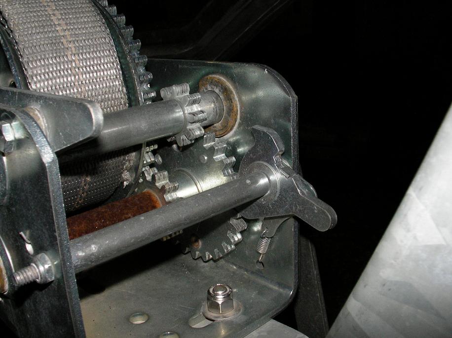
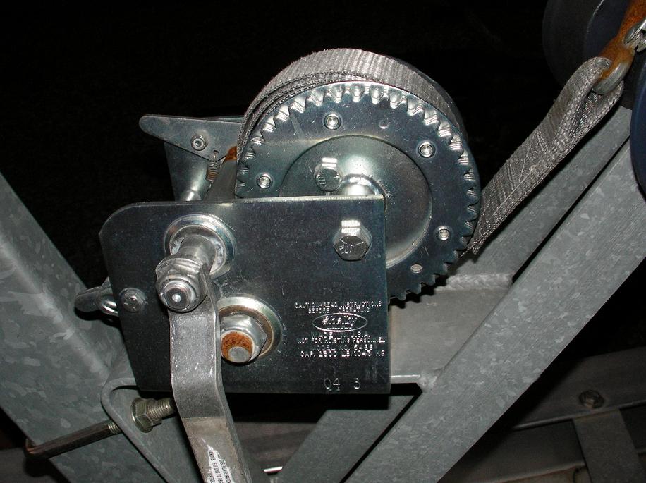
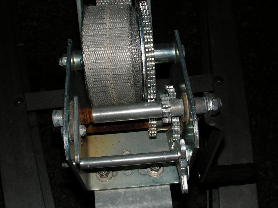
Aft Winch
Many thanks to Brandon for bringing us a second winch. Smaller and just right for some serious pulling power on the aft deck. This winch has a 5″ diameter drum 14 inch flanges, 12 inches apart, capable of holding 100′ of 1″ line. The reduction ration is 23:1.
Build a Winch from Scratch
Step #1 Get an Example
Brent Swain has a design for a simple anchor winch in his book, and it’s a perfectly good design for the most cursing boats but as RV Seeker is more work boat than cruising sailboat, I want a winch that has a few more capabilities, but I still don’t want one of the fully electric or hydraulic commercial units you see on trawlers. Besides, we can’t afford one of those anyway.
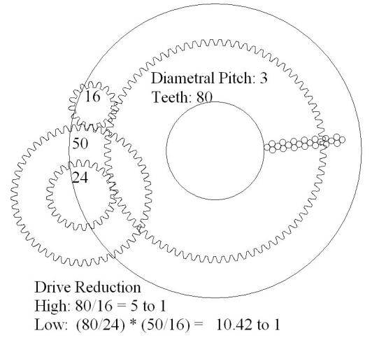
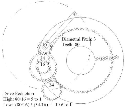
Out in my front yard was an example of a two speed manual trailer winch that will serve as a model for our anchor winch. The handles shaft can slide sideways when the latch on the left side is up. The small gear on the handle’s shaft is either neutral, high speed or low speed. Spool gear: 42 teeth, Jack shaft gear; sm: 14, lg: 26. Crank: 9
A ratchet pawl on the far side
prevents backwards travel.
The crank handle shaft can slid
sideways when to lever on the
opposite side is lifted.
The handle shaft is slid to the
center position so the gear on the
handle shaft is not engaged. This
is the neutral position.
Example of a narrow spool that allows the cable to neatly layer on without assistance.
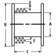
Step #2 Drum Design
A great tool is Ingersoll-Rand’s: Drum Capacity Estimator
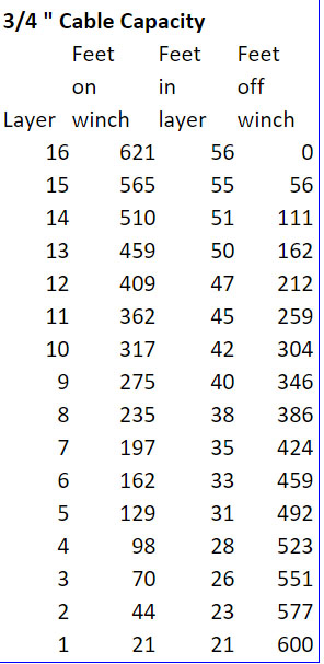
We want to be able to carry 500 feet of 3/4″ steel cable on the anchor winch that will give us over 25 tons of working load. Our drum turns out to be tall and thin, mainly due to the distance between the bow and the drum which is about 8 feet. The drum will be: (A) 12 x (B) 36 x (C) 5.5 inches and carry a working load of 500+ feet of 3/4″ cable. The details for the spool’s capacity are listed in the chart, ‘3/4 ” Cable Capacity ‘.
With the handle shaft pushed all
the way in, the gear on the handle
shaft is engaged in the high speed
position.
Moved all the way to the right,
the gear engages with a jack
shaft with the low speed gears.
So the plan is to draw a plan based on the two speed manual winch that is on lots of boat trailers, and building something similar but much bigger with the addition of a crude brake and the possibility of powering it with an gear reduction or hydraulic motor. We’ll have two of these units on the bow. The second will have smaller cable.
The boat winch reduction gear reduction calculates as follows: Spool gear: 42 teeth, jack shaft gear; small: 14, large: 26, and the crank has 9 teeth. So high speed is; 42/9 = 4.66 to 1. And low speed is 42/14 * 26/9 = 8.66 to 1.
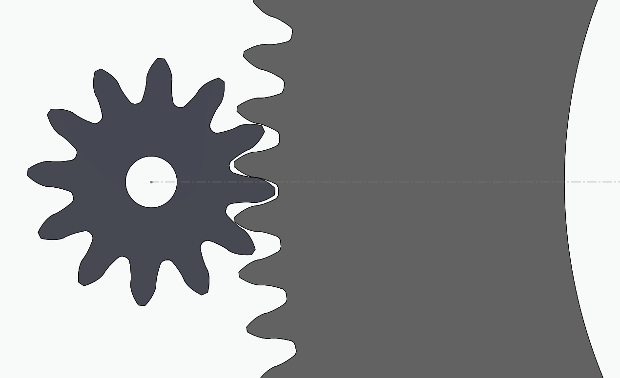
Step #3 Spur Gear Design
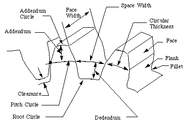
Forest Moon offers a free program for generating DFX files for specified Spur gears: www.forestmoon.com/Software/GearDXF Or you can use http://woodgears.ca/gear_cutting/template.html online application if you can convert from HPGL. If you’ll need ring, rack or pin gears then for $26 you can get the full downloadable version of the Gear Template Generator program from http://woodgears.ca the outputs to DFX. I got the Gear Generator program from http://woodgears.ca because it will do inner ring grears, but the current version (2.05) calculates diametric pitch (DP) incorrectly, so if you need to covert DP to Pitch Diameter (PD) which is simply PD = Number of Teeth / DP. It also generates teeth with no Dedendum. So the best course of action is to generate all of your gears with the same program to help insure they work nicely together.
Need a quick lesson on gear ratios? See: http://www.teamdavinci.com/understanding_gear_reduction.htm
Gear Formulas: www.engineersedge.com/gear_formula.htm
PD = Number of Teeth / DP
DP = Number of Teeth / PD
40 ton holding, 7 ton pulling
18.57:1 ratio Nabrico winch.
12.75″ D x 11.25″ W drum
holds 176 ft of 3/4″ cable.
Version #1
The first step is to simply scale up the boat winch design so that it fits on the the 36 inch tall drum for the cable. We also adjusted the reduction ratio to favor more power. Normally only 200 feet of cable will be used which is only the first 4 layers of cable on the spool, with about 50 feet and 7 (5.5/.75) wraps per layer. With a 5 to 1 drive with the high speed gears it will take about 7 wraps x 5 times gear reduction x 4 layers = 140 turns of the crank to real in 200 ft of anchor rode.
The maximum load on the boat winch is about 2000 pounds. The working load for 3/4″ steel cable is about 12,000 pounds (Source). The boat winch handle is 7 inches long, 2000/7/12 = 23.8 foot pounds. With a 19″ handle on the upscale winch it would be about: 12,000/19/12 = 52.6 foot pounds; doable but not easy. 35 pounds is considered the maximum recommended force to move a helm.
Version #2
Close to the same reduction ratios can be achieved with proportionally smaller gears which save weight, steel, and room. And another gear can be added that will allow a motor to dive the winch as well as the hand crank.
Another Example
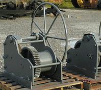
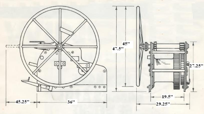
I found a rebuilt Nabrico 40 ton winch for $2,800. These are mainly used a towing winches that raft together barges. It has a 7 ton pulling capacity with the 18.57:1 reduction.
Version #3
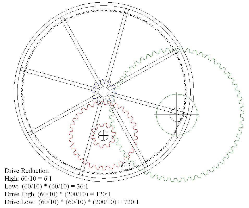
A hand wheel was added and the gear ratios changed to provide more power. The hand wheel is also an internal ring gear that can be optionally powered by a hydraulic motor. Turning by hand the high speed is 6:1 and the low speed is 36:1. So it will take 42 turns ( 6 x 7 warps) to pull in about 50 feet. In low speed, it will be able to pull with more that 7 tons for force.
Calculating a Bearing
Bearing performance is measured in pressure and velocity or “PV”.
Solving for a working load of 10 tons on a 3″ shaft with a 6″ bearing (3″ on each side) turning at 60 rpm:
V in feet per minute = 0.262” x RPM x diameter
= 0.262” x 60 (rpm) x 3″ (shaft)
= 47.16 fpm
P = total load / ( shaft diameter x bearing length )
= 20,000 lbls / ( 3” [shaft] x 6” [bearing length] )
= 20,000 lbs. / 18 sq in
= 1,111 psi
PV = pressure x velocity
= 1,111 psi x 47.16 fpm
= 52,394
You can also use Oilite’s bearing calculator: http://www.oilite.com/bearingCalc.asp You can increase the area to reduce the PV if needed, but anything under 75,000 will not be hard to find if the P is under 4000 and V is under 500. See: www.buntingbearings.com/data.html for some ideas.
Add a Motor?
The path of that 19″ handle makes a circle with a circumference of about 119 inches ( C=dPi, 19 x 2 x 3.14). If we added a great that size it would have 108 teeth on it and it could be driven by a 16 tooth gear. A 2 hp DC motor from a treadmill is going to spin at about 4500 rpm. The large crank gear will then move at 666 rpm ( 4500 * 16 / 108 ). That’s about 10 turns per second! Way too fast. So we need more gears and the best answer is likely a planetary gear set like is found on off road automotive winches. Harbor Freight has a 5000 pound winch with a 294 to 1 planetary gear set and a 3.4 HP, 12 volt motor. With a line speed of 5.3 ft. per minute off a drum that is about 6 inches in diameter the RPM is about 33 ( 5.3 * 12 / 6 * 3.15 ). If we added an 8.5 inch diameter, 24 tooth spur gear to the drum and mesh that with the 80 tooth gear on the anchor winch drum, then the anchor winch drum would spin at under 10 rpm ( 33 * 24 / 80 ). Pulling in about 200 feet of rode in 3 minutes. ( 7 wraps * 4 layers / 10 rpm)
Sail Winches
Junk Rig sails are heavy but extremely easy to manage. A block and tackle is often used to raise and lower the sail which in our case will weigh about 800 pounds. This can be done with block and tackle but will still be a significant job. According to Piratical Junk Rig the best answer would be two sets of 5 part blocks. The disadvantages of blocks is the amount of line one the deck once the sail is up, the fact that two people are needed to raise the sail, and that it is difficult to automate. For those reasons we have chosen to use a single halyard to raise the sail and to put the lifting work onto a winch at the base of each mast. Their are such winches on the market but besides being expensive they will be more complicated to repair as we can not easily make all of the parts, and they provide no option of adding a hydraulic motor to drive them.
Rene Sejler’s Top Lift
A great DIY design came in from Rene Sejler Halyard-Topping-Lift-with-Brake-and-Role-Pulley, and it’s actually a spool. It also looks like it would be something that we could add a hydraulic pump to.
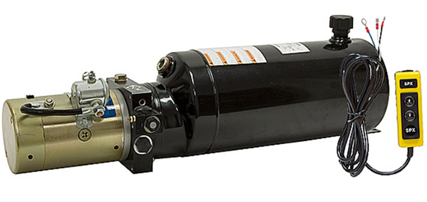
12 VDC 1.3 GPM 2500 PSI
Another route is to possibly start with a hydraulic wheel hub motor and use it’s shaft and bearings. An advantage of this design is that the spool is open on one side so it is more like a capstan allowing the line to be removed and quickly transferred to a backup winch if needed. Down below there would be a small DC hydraulic power unit, and that would drive a hydraulic hub motor normally used on a lawn tractor.
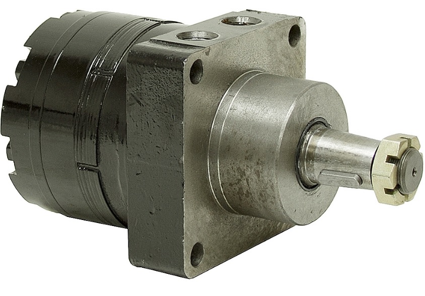
Hydraulic Wheel Motor
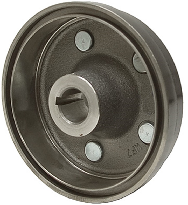
5 BOLT WHEEL HUB
The fabricated parts would consist of the same bits found on Rene Sejler’s winch less the center shaft. The hub can fit inside a 10 inch diameter pipe that would form the spool drum. A 1000 pound load on the halyard would need 6000 inch pound. A 12 cu in motor will provided 6300 inch pounds. The 1.3 gmp pump delivers 300 cubic inches per minute. So the 12 cu in motor will rotate 300/12= 25 rpm. A 12 inch diameter pipe will hold over 3 ft per wrap. A 12 inch wide spool will hold 16 wraps or about 50 feet of 3/4″ giving the total lift time of about 30 seconds. And double braid dacron has a 1375 foot working load.
Pump Wiring
Pump Details: 2500 PSI at 1.3 GPM, Built-in cartridge check valve, Adjustable relief valve set at 2500 PSI, 12 VDC motor, 270 amps, Ports SAE 6, Intermittent duty, 2.5 gallon reservoir (1.6 gal. useable) with inlet strainer, magnet, and filtered breather, Dim 25″ x 8″ x 7″
Motor Details: Model BMER1-200-WS-T4-S, Disp. 11.96 cu.in./rev., Pressure 2973 PSI (Cont.) 3481 PSI (Int.), Torque 4691 in-lb. (Cont.) 6310 in-lb. (Int.), Speed 330 RPM (Cont.) 425 RPM (Int.), Flow 18.5 GPM (Cont.) 22.4 GPM (Int.), Rotation Reversible, Mount 4 Bolt Wheel, 5.812 bolt circle, 3-1/4″ pilot dia., Shaft 1-1/4″ tapered x 4.21″ shaft w/5/16″ key and threaded end, Ports SAE 10, Size 4.94″ x 5.25″ x 5.45″
Manual/Hydraulic Sail Winch
For brakes; Zack, one of our crew that work on motorcycles, found that a 2010 Yamaha Grizzly 350 ATV with a hub that measures 6.29″ diameter and 1.14″ width. (160mm x 29mm) is a good match for the hub.
3/4″ Double Braid Dacron with a working load of 1375 pounds
Design Features
1) Operated on hydraulics from the pilothouse or automatically by a computer that is monitoring heal and wind speed.
2) Operated on hydraulics from the winch by activating the electric hydraulic valve.
3) Operated manually without any reliance on hydraulics.
4) Open spool / Capstan so the line can be moved to or from another winch.
5) Able to freewheel so the line can be played out using the brake
6) Mechanical break – not reliant on the hydraulics.
7) Mechanical crank with reduction gear that is not reliant on hydraulics.
8) Designed so that the non-hydraulics components can be cut on a CNC plasma table.
9) Designed to hole a minimum of 40 ft of 3/4″ line on a single layer.
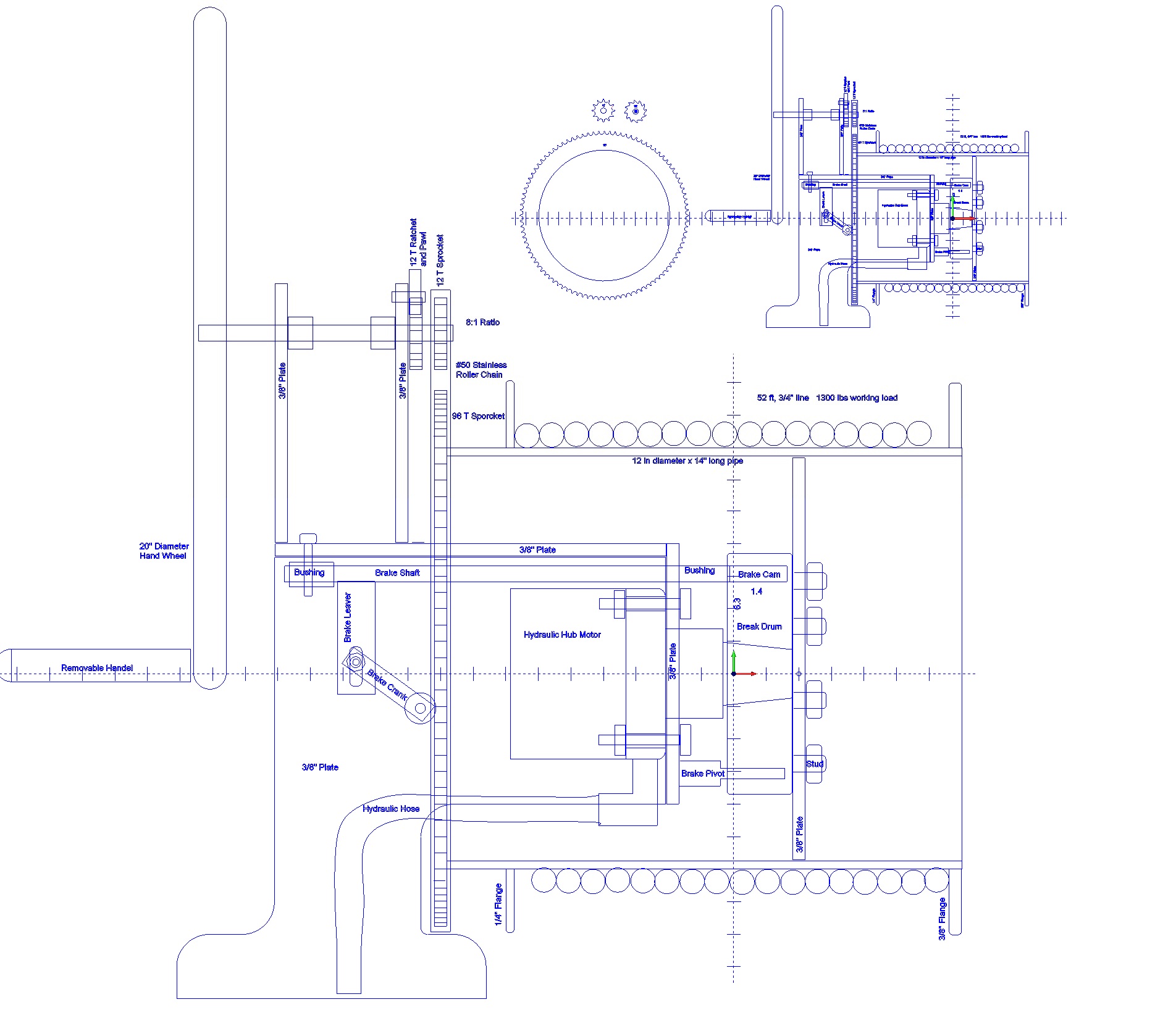
Version 2 of the design uses CNC plasma cut gears in place of a roller chain and sprocket system and uses a spring to set the brake and a small hydraulic cylinder or manual leaver to release the break.
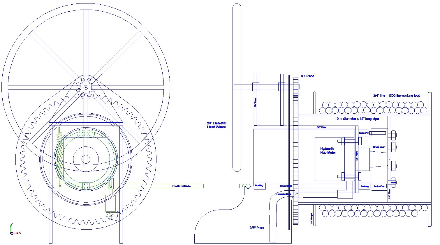
Sail Winch V2
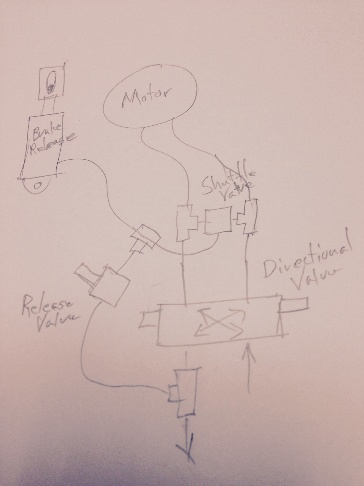
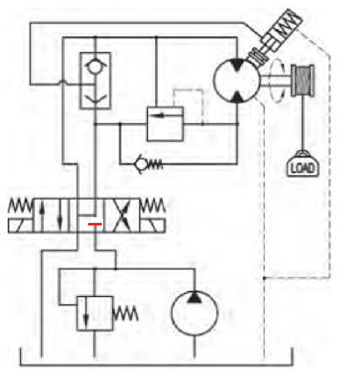
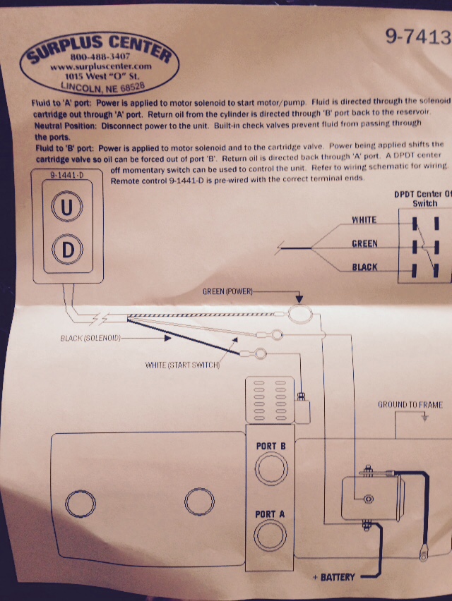
Winch Valve Schematic
The hydraulics are something I am learning. The valve is a solenoid activated directional control valve that when centered would connect the two output ports so as two allow the motor to freewheel. A spring sets the break and a small cylinder releases the break. And the break should be set before the directional control valve allows the motor to freewheel. Hence those processes may need to be separated
Gears V2
We cut gears on our CNC plasma table. If we can make them work, they will save us the cost of having to use stainless steel roller chain on sprockets that are CNC plasma table cut. Gears however are less forgiving to the inaccuracy of the plasma torch, but Drew Morgan has a cleaver suggestion of running the gears for days with a mixture of marine grease and sand so as to grind the gears into a better fit. He also provided a better gear design that we will use in the next version of the winch.
Cycloidal Gears
“Involute gears (which is what you have right now) are usually used because they’re much easier to make on a hobbing machine, and you can mix-and-match them as long as they’re all the same pitch. You don’t really care about those two advantages for this application, though, since you’re CNC cutting them and you’re not going to be swapping in various other sizes of gears after the winch is put together.
I added one tooth to the large gear so that it has a prime number of teeth. That may be especially helpful if you decide to do the process of running-in with gritty grease and a motor hooked up to the pinion for days. (with a 97 teeth on the large gear, every tooth of the small gear will hit every tooth of the large gear, forcing everything to wear down to a uniform shape. with 96 teeth on the large gear, every tooth of the pinion will hit only the same 8 teeth on the big gear every time, and if you ever take apart the gear set, you’ll have to time the teeth back up to hit the right spot for the teeth to match back up)” –Drew Morgan
Download Here: Cycloidal_gears_8to1.zip
Resources
Drum Capacity Estimator: http://www.ingersollrandproducts.com/lifting/winches/drum.htm
Example: http://motivationdocksupply.com/winches/hand-winches.php
Brands: Beebe, Tulsa, Braden, Garwood, Hyster, Thern, Nabrico