I started off making parts for the submarines with a Mini-Lathe. I doubted I would save enough money to offset the $800 investment but I was wrong.
While this is most likely the least used tool in my shop it is one of the most indispensable for making parts that seal with o-rings, the odd PVC fitting, a perfectly round hole in a jig or for just polishing a cylinder.
It took a few years but it actually paid for itself. When I recently moved up to my $3000 Grizzley 12×36, it paid for itself on the very first part.
Starting small is a great idea, and if you move up you’ll still have the small one that you can let the friends and family use.
www.mini-lathe.com is a great web site if you want to look more at the small lathes and accessories available.
Turning Stainless Steel
If you want to save money then visit your local scrap yards. I needed stainless steel round bar in order to make wheels for the boats ballast sled and found a 1.5 inch x 8 foot piece of 400 series stainless at the local scrap yard for $48. The price from Online Metals is over $70 + Shipping.
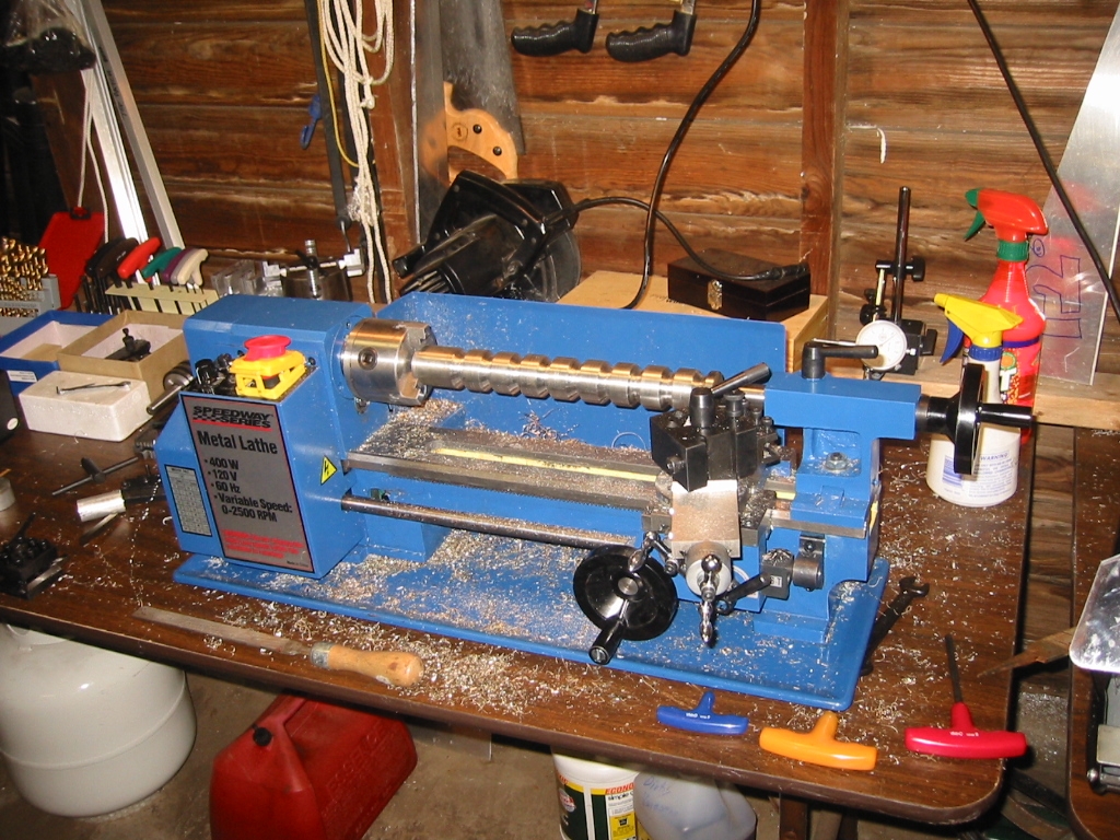
(1) Turning 1 1/2″ stainless steel bar to make V-groove wheels.
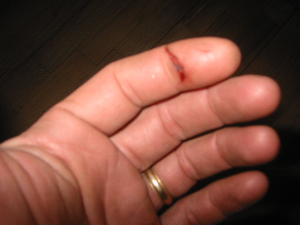
(3) Nearly lost a finger tip. Don’t try to clear the scarf while the lathe is running. That’s likely in the safety instructions I threw in the trash.
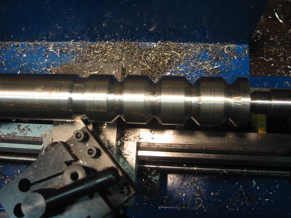
(2) V-groove wheels.
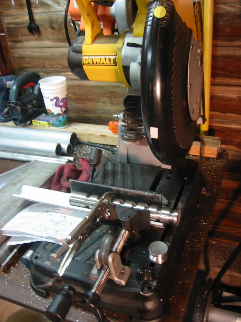
(4) Cutting the wheels apart in a cut-off saw.
(1) After a little practice with aluminum I set out to make the wheels for the ballast sled. The sled will weigh over 1 ton, and weight is a plus so stainless steel made sense but it is a lot harder to work with than aluminum. Surprisingly you can cut it with the same HSS steel bits used for aluminum, but is it necessary to sharpen them frequently. I gave up on facing the outside of the bar and just settled for getting it close to parallel to the bed.
(2)The real tick with stainless steel is to get the cut deep and keep the cut moving. Each cut needs to remove a piece least as thick as paper. This will often come off in a continuous ribbon of steel. The bad thing is that the deep cuts mean that the surface will not be very smooth and a file will not do much to help, but I’m making wheels and not pistons or valves.
(3) The other bad thing is that the steel shavings are sharp and long. Long enough to get snagged in the chuck and turn your lathe into a ban saw. I made the mistake of trying to clear one of these long shavings with my bare hand. About the time I grabbed it, the other end got tangled in the jaws. I still have my finger, but I don’t have any feeling in it. Now I always either shut down the lathe or clear the shavings with a screw driver or brush. I sometimes wear gloves but it goes against common advise which stays you should not wear gloves, long sleeve shirts, rings, watches or other jewelry that might get tangled in the lathe or work piece. A good suggestion came to me from a real machinist who pointed out that a groove type cutting tool would eliminate the problem by causing the shavings to break up into short pieces. It’s well worth pursuing while you still have fingers to turn the pages of the “Machinery’s Handbook“
(4) I paid a $120 at an auction for the 14 inch DeWalt Cut-Off Saw and it has been handy for cutting aluminum strips of sheet and aluminum pipe, but it is indispensable for cutting steel, even if the new blade did cost another $90. It cuts through an 1 1/2 inch stainless steel bar in about 15 seconds with light pressure and generous quantities of WD-40. However the blade does have a short life before it need to be sharpened at a cost of $50. After 12 cuts through 1 1/2″ stainless steel, and the equivalent of 40″ of 1/2″ plate steel, the blade was past ready to be sharpened. No telling how long it would go if I would only stick to cutting aluminum.
Milling on a Mini-Lathe
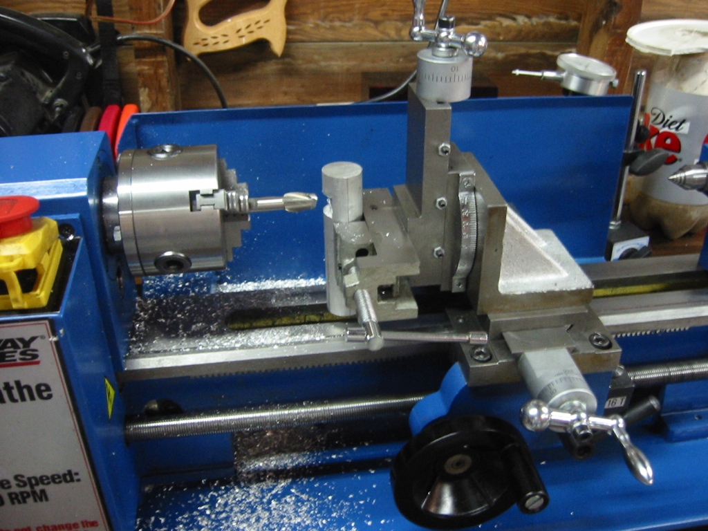
Mini-Lathe setup as a mill.
The mini lathe can be converted into a mini mill. Details are on Varmint Al’s site: www.varmintal.com However the conversion requires considerable time to setup, and its not very ridged so do not plan on using it on steel.
It’s not a complete waste of time if you are only going to need a mill infrequently and only on small items. Otherwise, it’s a better idea to save your money and invest in a real mill.
External O-Ring Grooves and Snap Rings
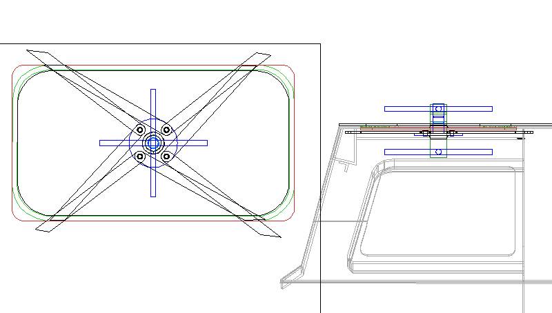
(1) Quick acting hatch.
I finally settled on a top hatch design. It’s the most critical part of an ambient submarine because unlike a normal 1 atmosphere submarine, this hatch wants to blow outward and not inward. For this reason I was glad to discover that it is not too inconvenient to have the hatch open inward. But I did want the hatch to be quick opening and able to be opened from both the inside and outside.
(1) The first quick acting hatch design uses o-rings to seal a spindle. On the inside a wheel turns and drives four bars into slanted openings. This motions forces the hatch upward, sealing it against a neoprene gasket. Each of the four bars connects to the center wheel with a pin that is held in place with a snap ring. (2) The specifics that you need for the dimensions of o-ring grooves and snap ring grooves can be found on several sites. But the easiest and clearest explanation I found for o-rings was at www.everyoring.comand www.mcmaster.com has good info on o-rings as well as snap rings.
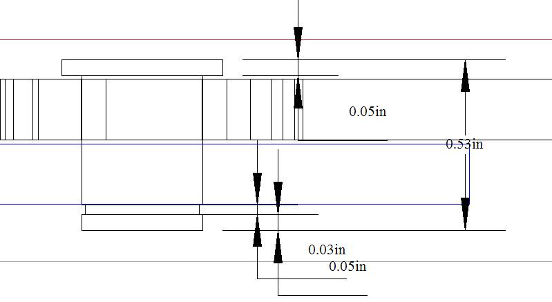
(2) Snap ring pin detail.
In short you need to pay attention to the amount of compression applied to an o-ring . Harbor Freight sells a kit of o-rings that are .118 inch wide. The width of an o-ring is a measurement of the rings cross-section. If the o-ring is going to seal on a shaft or axis that moves then it is dynamic and if it is .118 inch wide then it needs to be compressed 10% or .012 (.118 * .10) of an inch. If the shaft does not move or it is static then it needs to be compressed 13.5 to 25%. or .016 to .029 of an inch. Finally if the seal is not on a shaft or axial, such as a hatch ring, then compress it by 20 to 32% or .024 to .038 of an inch. In each cast the groove depth is .08 inch. Actually a hair deeper, up to .086 if it is on a shaft. The groove width is .15 at the bottom and .16 inch at the top. An exception can be made for hatch rings where you want the top of the groove a bit smaller than the width of the o-ring so the o-ring will be held in place when the hatch is open.
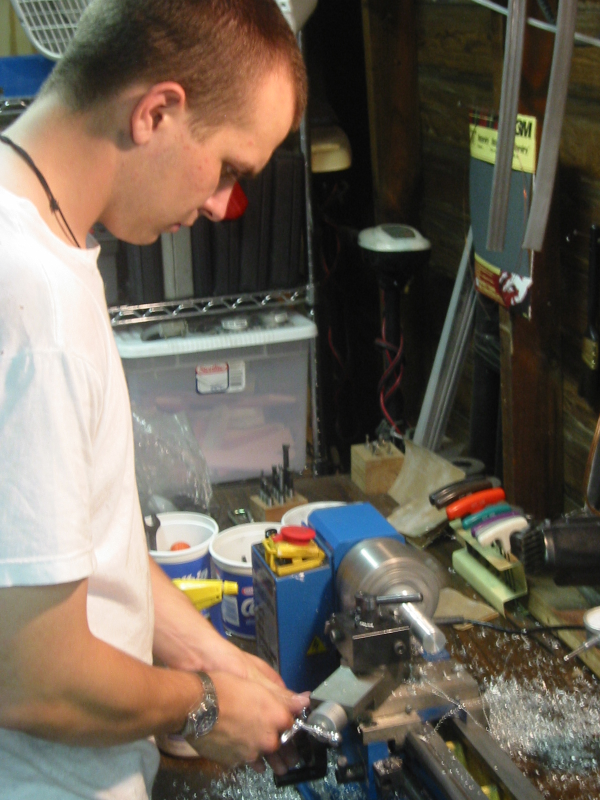
(3) Carl turning the hatch parts
For the top hatch the shaft is 1.04 inch and the groove depth is .086 inch. Since the o-ring is .118 the groove depth is .086 then .032 protrudes from the shaft. (.118-.086) Decrease that protrusion of .032 by the amount of compression needed or .012 and the compressing wall needs to be .02 inch (.032 – .012) from the shaft on both sides so the interior diameter of the compressing wall would be 1.08 inch (1.04 + .02 + .02).
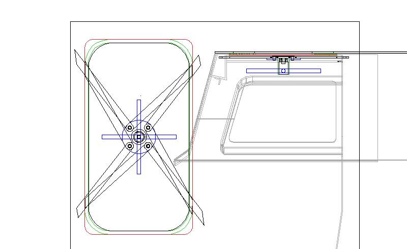
(4) Revised hatch design.
(3) Oops! …the hatch can’t open with an outside handle because there is no room for the handle once the hatch is inside. Unfortunately we had to build the parts and hold them in place before noticing the obvious problem.
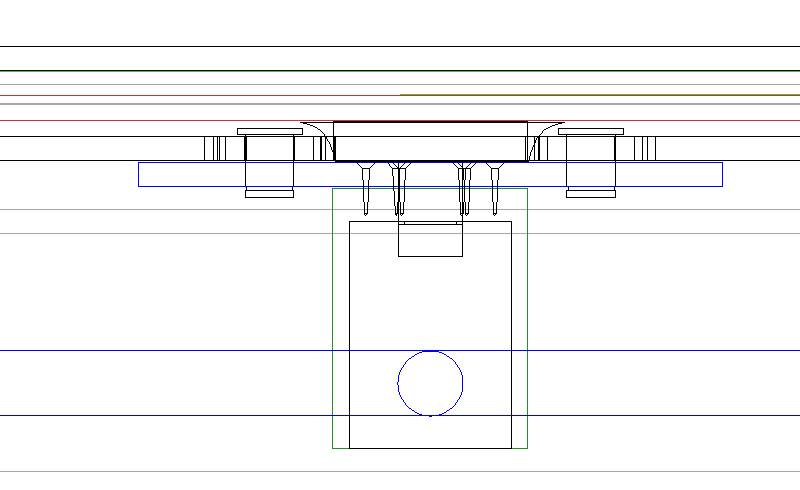
(5) Hatch handle detail.
(4) (5) So, now we have a new and hopefully last version of the top hatch, and Carl has a new set of plans. This design lost the external handle if access to the cabin must be done from the outside, it will have to be done through one of the bottom hatches. That will likely be better anyway as opening the top hatch inward will exposed the cabin to flooding. And even with the submarine on the bottom it is still possible to fit through the lower hatches.
Internal O-Ring Grooves
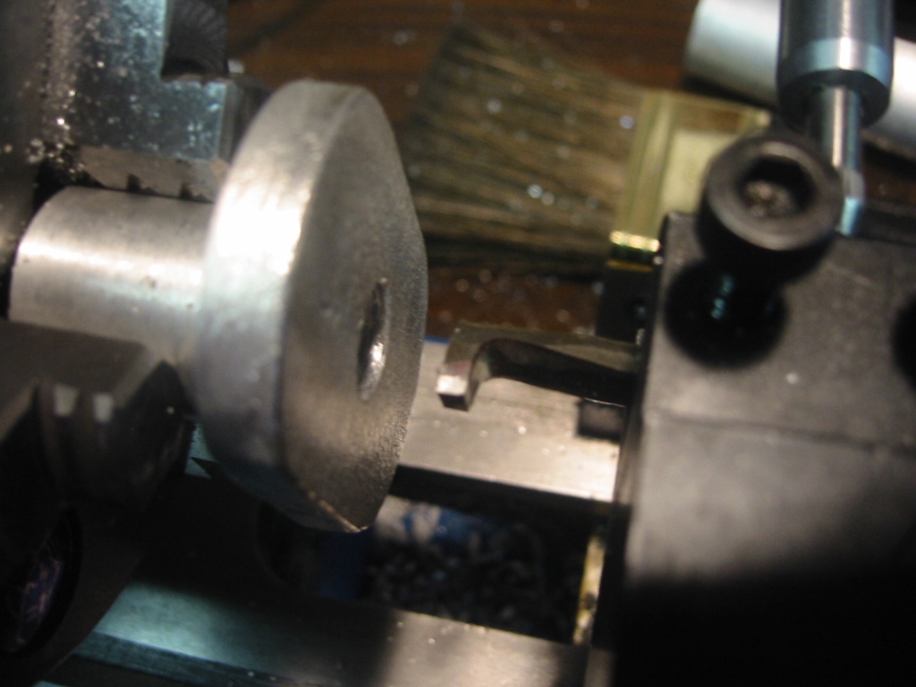
(1) Internal groove bit.
The submarine’s bottom hatches used several flanged bushings which have 3/8 inch stainless steel bolts that act as shafts to turn the latches. The shaft and the bushing need to be sealed with an o-ring. Since the bolt or shaft moves up and down I can not just simply cut a groove in it. (1) Instead I need to cut an internal groove for the o-ring inside the bushing.
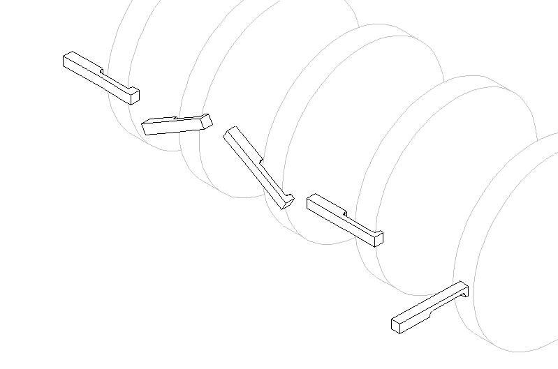
(2) Grinding steps for a bit to cut internal grooves.
(2) The trick was over coming the round edges on the grinding wheel. I first wanted to just grind the bit down by holding it parallel to the shaft to the wheel, but it is necessary to lift the tool so that it is at a 30 degree angle in order to grind out a cutting tip that is almost 3/16 inch deep. Then just the square up the last .1 inch of the tip.
(3) A standard o-ring groove is actually .09 inches in the bottom of the groove and .1 at the top so there is a very slight angle on the tip.
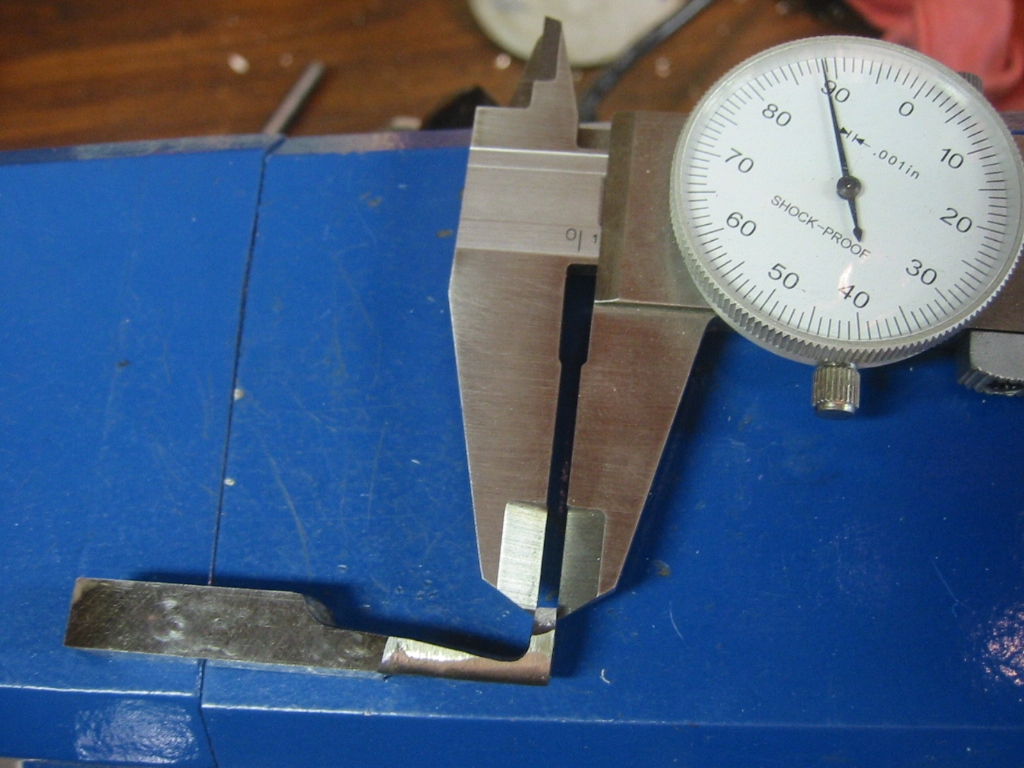
(3) Checking the groove bit.
Finally the end of the bit, and the outside edge of the tip can be ground so the tip is finished dimensions.
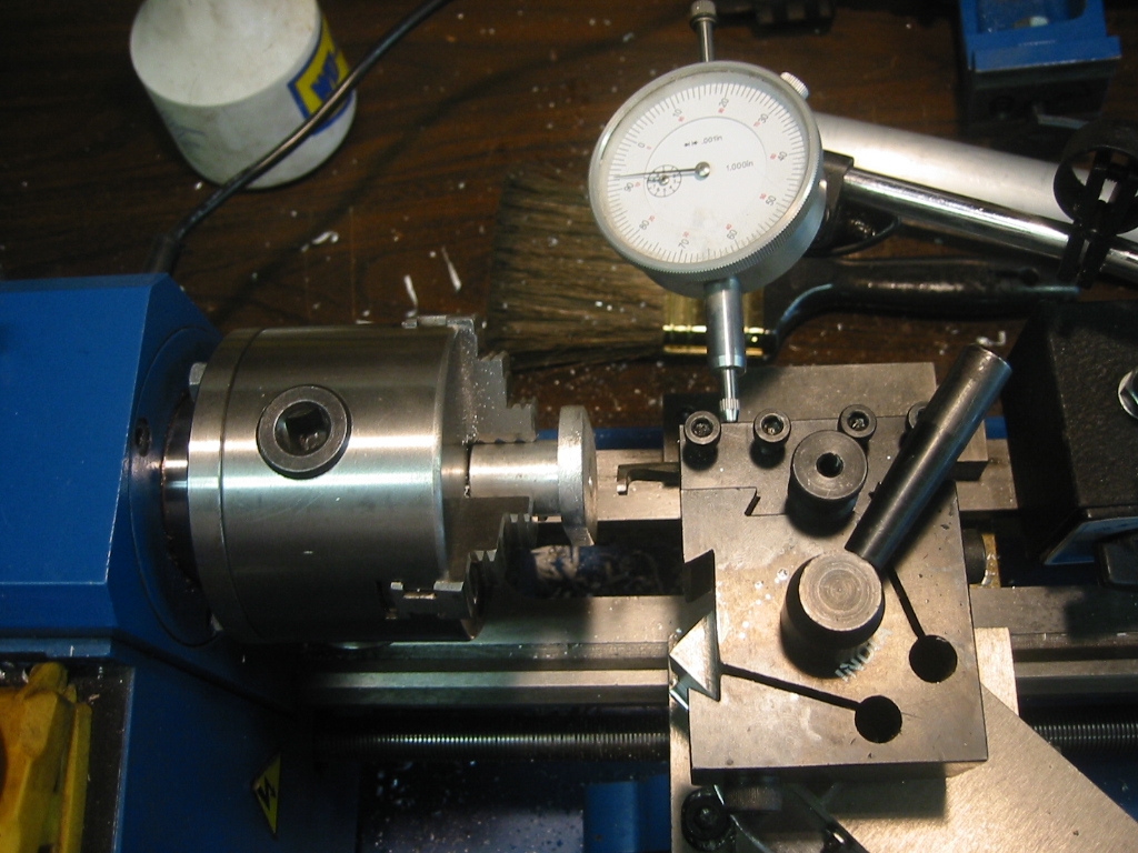
(4) Dial caliper setup to measure the depth of the groove.
(4) Once the bit has the exact dimensions of the groove, it can be inserted into the bushing so that it is just brushing the inside wall. Then it was only a matter of measuring the travel of the cut using a dial caliper. In this case .06 inch.
Grinding on the Lathe
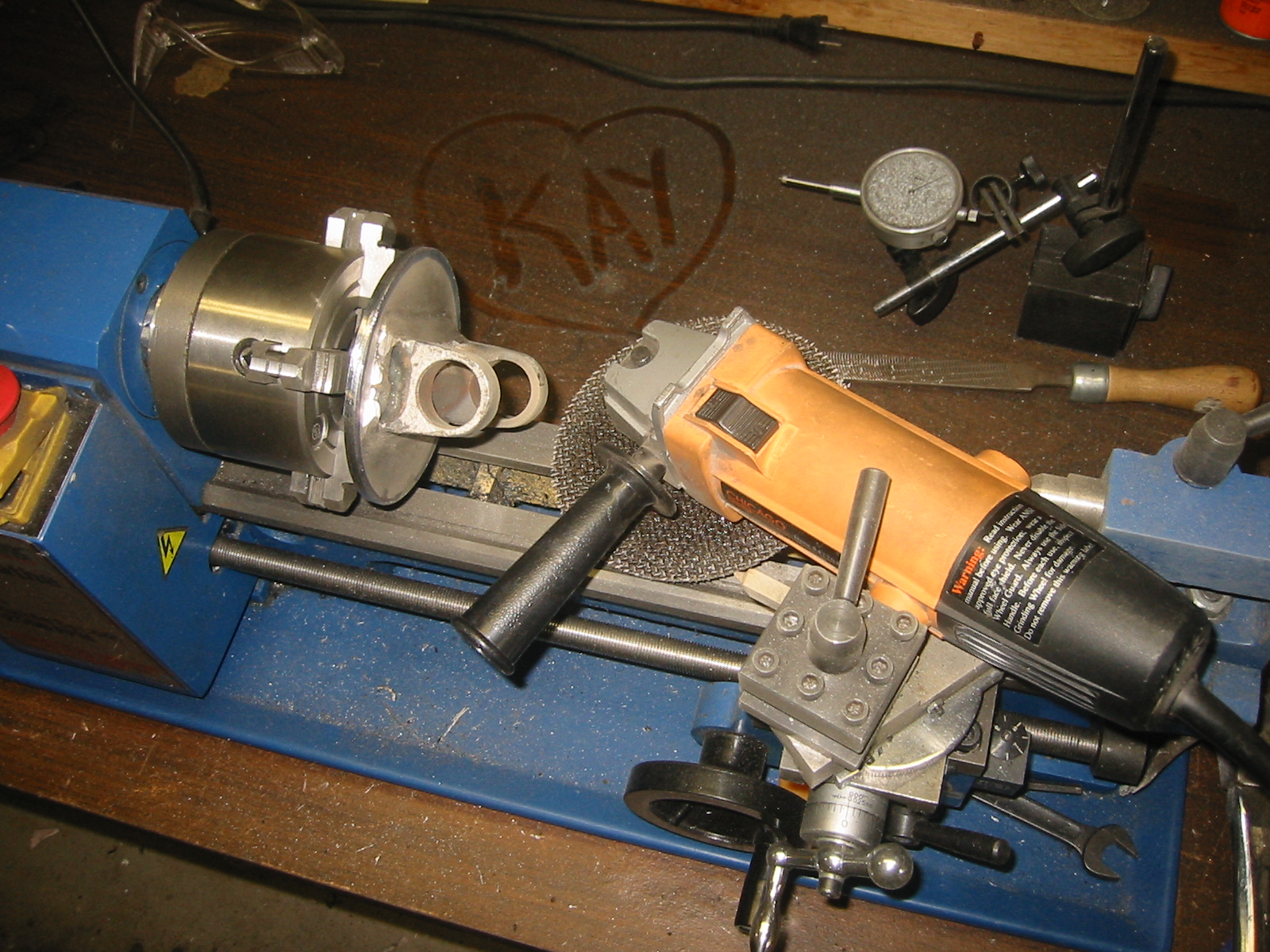
Stepping Up to a BIGGER Lathe – Grizzly 12 x 36 Lathe
Grizzly 4003 12×36 Owners Manual and Parts Manual
The Grizzly 12×36 comes with a Series 200 tool post. You’ll need to know that when you go and buy additional tool holders. The tailstock has a #3 morse taper.
The left and right hand carbide insert tool holders that come with this lathe are Grizzly part numbers: G7029 and G7028. The carbide inserts are G7040 and G7039. The tread cutting tool is the G7030 and the treading bits are G7041.
Links
Metal Lathe How-To Links:
Grinding Your Own Lathe Tools
YouTube: Turn Wright Machine Works
YouTube: mrpete222’s channel
www.mini-lathe.com Mini-Lathe – Great Site – specific to the Mini-Lathe and Mini-Mill
www.jjjtrain.com/vms/library.html Virtual Machine Shop — Great Site with Movies!
Lathe Tool Supplies
www.shars.com Shars
www.cdcotools.com CDCO
www.wttool.com Wholesale Tools
www.kbctools.com KBC Tools – Good Customer Service
Metal Stock
onlinemetals.com Expensive! Good place to check price before going to the scrap yard
www.metalsdepot.com dito
Mini-Lathe
Tool Supplies
www.varmintal.com Varmint Al’s – Very helpful site. I used his “Milling Attachment” info.
www.sherline.com
www.littlemachineshop.com Little Machine Shop — Prices are a little higher, but quality is good and shipping is fast.
www.harborfreight.com Good prices, shipping is slow.
Forums
http://groups.yahoo.com/group/7x10minilathe
http://groups.yahoo.com/group/7x12minilathe (On Topic Only)
