2.32CuIn Hydraulic Clutch Pump
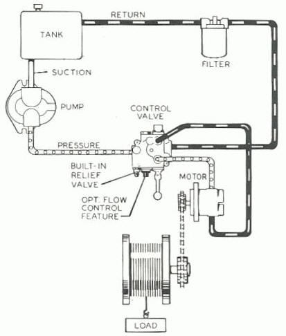
Hydraulic Power Units
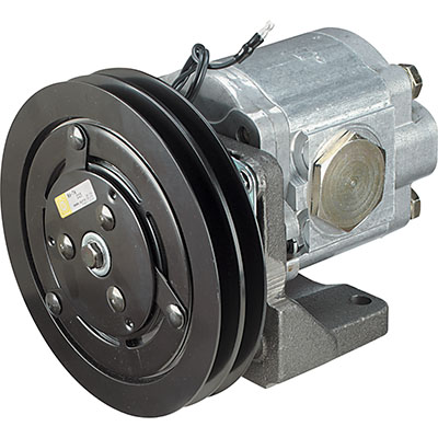
Main Engine Clutch Pump: The 200HP Cummins 5.9, 6BT main engine will provide power for a Northern Tool; High Pressure Hydraulic Clutch Pump, 2.32Cu In, Maximum pressure 3000 psi. 1 1/4in. NPTF inlet, 1in. NPTF outlet. 29.1 gpm @ 3000 rpm, 11.6 gpm @ 1200 rpm. About $520 It has a 2 groove, 7in. pulley that uses type A 1/2in. belts and rotates clockwise. It uses two Gates A49 1/2 x 51″ belts and can likely accommodate a 52″ belt.
VMAC Clutch Pump: 6 in 1 Multifunction VMAC with 10 gpm @ 3500 psi
DC Pumps: Two 24v DC Direct Drive Pumps, Model#: 123-8915, Input: approx 160 Amp at 24v, Output: 2.5 gpm at 1049 psi, max 2500 psi, 42 centistroke oil, Cost $300 each.
 Portable 10 HP diesel powered hpu with a pump to provide 5-6 gpm at 3,000 PSI will be on board that can be transported by tender for use in powering various hydraulic tools such as water pumps and cutters. This gpm can alternatively be used for an emergency supply while on-board.
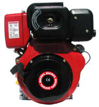
10hp Chinese Yanmar knock-off
The following formula calculates the hp of a pump:
( Pressure * Gallons per Minute ) / 1719 = Pump Horse Power
The Cummins 20 gpm, VMAC 10 gpm, and two 24v Electric pumps will all feed the pressure line. Each will have a pressure relief valve followed by an adjustable pressure switch controlled unloading valve and then a check valve before they connect to the pressure line. Each pump can then have it’s unloading valve set just below it specific maximum psi rating. As most of the components attached to the common pressure line are closed center the unloader valves will unload pump and optionally trigger a shutdown of the pump if unloader valve remains open for a set period of time. Except for the two 24v Electric pumps, the pumps will not be used in combination. The use of any pump will depend on the requirements of the load, and if the Cummins or VMAC engines are already running for some other purpose. The pressure switch under consideration for the unloader valves is the: 400_Series_HD_Switch (Noshok 400-1-2-300/2900-1). In addition to the pumps a large accumulator will provide relief from cycling pumps or frequently opening the unloader valve.
Unloading Valve
The first thing beyond each of the four pumps is a check valve to prevents any backflow from the other pumps, and next in the pressure line is an unloader valve. Because all of the hydraulic pumps are inexpensive fixed displacement pumps, they need to send the fluid somewhere and much of our equipment is closed center, meaning if the valve is not open their is no where for the fluid to go. So instead of burning up a pump or forcing all of the flow through a pressure relief valve, we simply add a pressure switch and once the pressure reaches 2400 psi we open a simple one way valve that dumps all of the flow back to the storage tank with no pressure. The trick is to add an accumulator to store some of he fluid at 2400 psi so when we open a valve to run a winch for just a few turns, the fluid comes from the accumulator. This will keep the unloader valve from constantly cycling. In addition we can add a timer the is triggered by the pressure switch and if the timer gets to 120 seconds and the pressure switch is still showing pressure on the system, then the timer can turn off the pump by disengaging it’s electric clutch or just turning off he motor in the case of the electric pumps. The unloaded valve is a simple one way valve attached to a tee in the pressure line one one side and the tank on the other side. It’s a normally open valve so without power to it just dumps from the pressure line to a line going to the tank. The one way solenoid valve it’self is is three parts; a body, cartridge and coil. The last part of the unloader valve is another check valve just downstream of the tee where the solenoid valve is. This check valve prevents pressure from flowing backwards out of the system when the unloader valve is open. And there will be lots of pressure and flow left in the system because of the accumulator.
Combine it with a tee and the check valve just down steam and we have a two way solenoid valve. Now put an adjustable pressure switch just beyond the check valve. And we have an adjustable unloader valve. Finally add a timer circuit that is triggered by the same switch and we can optionally turn off the pump or the pump’s clutch. So the chain looks like this using: Baum Valves and Filters H and NOSHOK pressure switch: 400_Series_HD_Switch.
- Hydraulic Pump
- Check Valve – Prevents prevents pressure from any other pump from flowing back into this pump. Example: Baum Inline Check Valve 3/4 C-1200-S 25 gpm, 5 psi cracking pressure. $68
- One way normally open solenoid valve on a tee so that it dumps any fluid back to the tank when the valve is not activated. Example: Baum DSH161NR 50 gpm, Normally Open Cartridge for 16 series $132, CCP012S Coil 12 Volt Spade connector 10 & 16 series $31, and LB10573A Body Cartridge Valve Body for 16 series ports 1-5/16-12 Thread $52. Total for the three valve parts $215
- Check Valve – Down steam from the tee is a check valve that prevents fluid backing up from the accumulator. Example: Baum Inline Check Valve 3/4 C-1200-S 25 gpm, 5 psi cracking pressure. $68
- Pressure Switch – Beyond the check valve is an adjustable pressure switch with the pressure set at 2500 psi, the maximum of the electric pumps and the lowest psi for all of the pumps. When the system pressure is below the pressure switch setting, the pressure switch closes and allows any power being fed to it, to pass onto the valve, closing the unloading valve and directing any from the pump into the system. Example: $160
Total cost for one unloader valve is $443.
A better alternative, and cheaper if the valve can be found at a discount is a electronic pressure switch that with two switch outputs that can be programmed with an window. We found a Hydac EDS 8476-2-6000-400, 6000 psi switch on eBay for $180. Part number is 921103 EDS 8000 The switch needs to be wired into power, as well as tapped into the pressure line, but once that is done it has an LED display and buttons to make selections from a menu where you can set the high and low pressure window to control the unloader valve.
Accumulator
Parker 10 gallon bladder accumulator. Parker-Hydraulic-Accumulator-Products-HY10-1630 The precharge gas is nitrogen to 90% of the systems minimum pressure, so about 1350 psi. Parker has a calculator for estimating volume, but the precharge and temperature plays a role so it’s just an estimate. But if we have a 10 gallon accumulator and we precharge it to 1350, then pump in oil to 2500 psi and can still use pressure down to 1500 psi, then we can get just over 2 gallons of fluid back. A 10 gallon accumulator is $700 to $1000 on ebay.
Pump Control
 The pumps need to be switched on if the pressure in line is below 2500, but once they are switched off after the pressure reaches 2500, they need to stay off until the pressure drops to a set value such as 1500 or what ever the minimum is for the specific task. Doing this will prevent the unloader valve and motors from constantly cycling on and off. However we’ll also like an over ride on the cut off pressure for those days when the captain shout “Give me everything she’s got.” For this we’ll need two pressure switches, one set to activate at 2500 psi and the other set to 1500 psi, and then will need a relay that hold the pump off until the pressure falls back down to 1500 psi. Thanks to Mike Miller for the help and the diagram.
How it works. The coil of the relay, CR1 has to be energized for the pump to get a signal. In reality that will be the unloading valve and the timer. But the on switch only has power if the 1500 switch is on because the system has less than 1500. But the 1500 psi switch does not turn the pump on directly, instead it turn on the coil in the relay. The rely turns on the pump but it also powers the coil using the second switch in the relay, latching the relay on. The relay will be powered off by the 2500 psi switch because that switch will simply break the connection to the coil.
The pressure switches can both be MPS25-1C-P5000A from www.automationdirect.com $94, Documentation: prosensemps25switches 500 to 5000 psig set point, 316 stainless steel piston sensing element, Buna-N O-ring seal(s), SPDT 3A, 1/4in male NPT process connection, 1/2in male NPT conduit connection with 6ft cable $94. And then a DPST normally open relay. $20
Optionally the pressure switches and relay can be replaced with a single pressure switch with dual set points. Example: Hydac EDS 8000 SERIES Electronic Pressure Switch can be programmed with a pressure range, Documentation: EDS 8000 EDS 8476-2-6000-400 goes to 6000 psi but at $180 on ebay is’s even cheaper that to dual switch approach.
The Six Hydraulic Consumers
There are six hydraulic components on the primary hydraulic system. A second hydraulic system includes the Hundested variable pitch propeller system that uses to Cummins 5.9 power steering pump to power the variable pitch control unit. The 6 components on the primary system in order from bow to stern follow: Anchor Winch including auxiliary ports, Deck Crane, Wash down pump, Sail Winch, Rudder, and Tender Winch including auxiliary ports.
1. Anchor Winch
 The anchor winch is a converted White truck winch that was powered by a pto. It’s now direct driven from a hydraulic motor. The smaller 6″ wide side of our winch has the most change from the first wraps to the last. We’ll take what we can get, but excellent would be 50 ft per minute on the first wraps, and it can be upwards to 350 ft/min on the final wraps. Keep in mind that in 1830 it took over an hour to raise the anchor.
The second task for this winch is to lift loads to the surface. For that duty a very high displacement and hence high torque motor is required. In this case the best solution we think is a two speed motor such as Parker’s Nichols Series 700 with a displacement of 12.9 or 25.8 Nichols Series 700 Documentation Ok, so Parker wants about $5000 for that pump, and that’s not going to happen. So, lets look at plan B. What if we had a 12 cu inch pump for hauling the anchor, which is 98% of the time, and a backup pump with 28 cubic inch displacement for the 2% of the time when we need to lift a big load. Some quick connects on the hoses and two bolts is all that would be needed. And common motors are less than $300 each.
Large Motor: Surplus Center 9-7080-375 24.0 cu in DYNAMIC BMSY400E2KS Hydraulic Motor. Seal Kit: Dynamic BMSY Motors Part Number: 61591
The winch calculation is (3.14pi *8.75 drum diameter) / 12in = 2.8 ft/revolution. 50 ft per minute requires 50/2.8=17.8 revolutions. The worm gear reduction on the winch is 29:1, so 18 revolutions of the drum requires 18 * 29 = 522 revolutions on the motor. So we want a motor that does around 522 rpm with 20 gpm off the main engine in order to raise anchor.
231 x flow rate (gpm) / Motor Speed (rpm) = motor displacement (cu ins/rev) or 231 * 20 / 522 = 8.85 cubic in.
Hydraulic motors are categorized by their displacement. For example an 25 cubic inch displacement motor uses 25 cubic inches of fluid per revolution. Small displacement motors run fast, and large displacement motors have more torque. Gallons per minute * 231 cubic inches per gallon / motor displacement cubic inches = motor rpm. At 20 gpm a 12.9 cubic inch motor is: 20 * 231 / 12.9 = 358 rpm. And at 20 gpm a 25.8 cubic inch motor runs at 20 * 231 / 25.8 = 179 rpm. For the Series 700, it’s exactly half the speed and twice the torque.
At high speed or 358 rpm the the worm drive reduction will reduce the rpm to: 358/29 = 12.34 rpm. The chain speed will be: pi * drum diameter / 12 inches: 3.14 * 8.75 / 12 = 2.29 feet per wrap * 12.34 rpm = 28 ft per minute on the beginning wraps, and much faster on subsequent layers. 3.14 * 16 / 12 * 12.34 = 51.6 ft per minute. The actual will be about 20% less due to losses in efficiency, but we should average about 30 ft per minute.
The motor will provide approximately a maximum interment torque of 7463 lbs in less 15 inches for the drum, times 29 for the worm gear reduction, less about 20% for loses and the pull on the line will be approximately: 7463 /15*29*.8= 11,542 pounds.
Anchor Winch Motor and Control Valve: Closed center, 20 gpm, directional control 12v solenoid valve, In parallel, a manual directional 6 gpm valve will allow slow movement control of the winch load. Also located beside the valve will be quick connect ports with a manual ball valve on the pressure line for any auxiliary equipment such as pumps.
2. Deck Crane

Auto Crain is based right here in Tulsa, Oklahoma. With 80 feet of cable on the winch, a lifting capacity of 2,500 pounds at 10 feet, and 1,250 at 20 feet, this crane will give use access over both the port and starboard sides of the boat. It’s an open center, and requires 6 gpm at 2,350 psi. Manual ball valve on the high pressure line will enable the crane hydraulics.
3. Wash Down / Emergency Bilge Pump
The pump is a Spacesaver 22780-0-01. It’s 6 gpm ? hydraulic water pump located in the engine room, will draw from the sea chest or alternatively from the engine room bilge. This pump will activated by a 10 gpm ? solenoid valve.
4. Sail Winch
Harken 70 winch with a clutch connected 4 gpm @ 2000 psi, open center, 2 speed pump, with 2 foot switches to activate each speed. A solenoid valve will activate flow to the pump if a closed center alternative can not be found. The cost of a Harken motor and clutch is over $2500 so we will likely look at adapting an off the shelf motor and using a valve the allows the motor to free spool in the closed position. Harken_MRW-01_70-2st_EHY
5. Rudder / Autopilot

1000 pound Fish Tail Rudder
At 60 tons, 62′ water line and 23 square feet of rudder the rudder post will see loads up to 21,000 foot pounds. The primary steering will be a manual chain and cable system, but hydraulic cylinders will also be attached to the rudder quadrant to allow the boat to be maneuvered with hydraulics from the helm or with a autopilot. Hydraulic cylinders are welded, double acting, 3.5″ bore, 20″ stroke, 1.75″ rod, clevis, 30.25″ retracted, 50.25 extended, SAE 8 port, 28,800 lb column load. pi * (3.5/2)^2 * 20 * 2 = 385 cu in. It is understood that the autopilot will not be used in rough sea conditions and so the duty cycle will be 25%. The control valve can be a Bailey 220315, 3 position spring center motor, float: parallel, 40 gpm, 12v.
6. Tender Winch
The tender weighs approximately 1,300 pounds and is suspended from two davits. It is raised by straps connected to the tender’s bow and stern. The straps pass through a single block pulley on the davit and down to spools on a common pipe shaft across the transom. A #60 roller chain sprocket is welded to the shaft. It’s approximately 8″ in diameter and 34 tooth. The shaft pipe is 2.5″ diameter, and about 3.25″ with a few wraps of the strap. The flanges on the spools are 10″ diameter and the load will increase diameter with wraps of the strap until it reaches about 9 inches in diameter. There is 16 feet of travel required to raise the tender from the water to it’s highest storage point on the davits.
The size of the hydraulic motor is determined by the torque required to lift it. The speed will be determined by any psi left over. The tender weighs less than 2000 lbs, but we’ll add a safety factor in right off the bat and call it 3000 lbs. Then straps have 3000 pound of load but as the spool fills the load is further and further from then motor. When the the spool has all 16 feet of strap on it it’s about 9 inches in diameter, so about 4.5″ away from the center of the motor. Our 3000 pound and 4.5″ of leverage so 3000 * 4.5 = 13500 in-lbs. Which is good, because they make motors with that much torque. But we can use the advantage of the sprockets too. The spool shaft has a 34 tooth sprocket, and if we put a 13 tooth sprocket on the motor, then the motor has to convert some of it’s speed into torque at the ratio of 13/34. And 13500 in-lbs * 13/34 becomes 5162 in lbs.
Surplus Center has lots of motors available and the larger the cubic in displacement per rotation means that more fluid flow is being converted to torque instead of speed.
Choosing a 21.2 cu in White Hydraulic Motor $229.95 It produces 8150 in lbs at 3000 psi. Our system might go as low as 1500 psi before the pumps kick in so we can adjust 8150 in lbs by 1500/3000 or 8150 * 1500/3000 = 4075. A little more would be closer to our estimated 5162 in lbs requirement, so we’ll look again.
A 23.87 cu in Dynamic BMK6 Hydraulic Motor 9-8665-400 $566.60 produces 10266 in lbs at 2900 psi. Even when the psi is reduced to 1500, it will still produce: 10266 * 1500/2900= 5310 in lb. It can work at 2900 psi with is over the 2500 maximum psi for our system so it looks like a good choice. Shaft: 1-1/2″ dia. x 3.01″ shaft w/5/16″ key tapped 3/8-16 Sprocket: 1-2125-13-K A #60 roller chain has a working breaking load over 9000 lbs but a working load is suggested at 2000 so a dual sprocket would be better.
https://www.usarollerchain.com/D60BS23H-Sprocket-ANSI-D60BS23H-Sprocket-p/d60bs23h-1-12-sprocket.htm
Speed: The motor above has a displacement of 23.87 cubic inches, so for ever rotation is used 23.87 cubic inches of fluid. There are 231 cubic inches in a gallon. Our system will produce a minimum of 2.5 gallons per minute, so the slowest this pump will run is 2.5 * 231 / 23.87 = 24.19 rpm. The spool turn slower because of the reduction in the sprockets. The spool turns 24.19 * 12/34 = 8.5 rpm. 16 feet of strap requires 21 wraps around the spool, so the longest recovery is about: 21 / 8.5 = 2.47 minutes. Not bad for a pleasant day, especially considering that you are not having to heave it up with block and tackle. But in rough seas, you’ll want to fire up the main engine and turn on the 20 gpm pump. 21 / (20 * 231 / 23.87 * 12/34) = .3 minutes, about 18 seconds.
Filter
????????? Donaldson HBK05