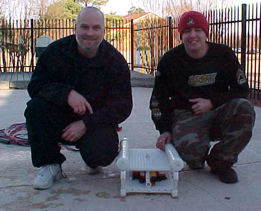
Doug, Carl and BOB
My first ROV, “BOB” is based on the “Sea Fox” design which is presented in Build Your Own Underwater Robot and Other Wet Projects by Harry Bohm and Vickie Jansen. This book is intended for younger ages but it is a good introduction if you are new to ROV’s. BOB’s improvements over the Sea Fox included the addition of a video camera, improved forward thrust and a joystick which greatly simplified control.
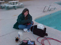
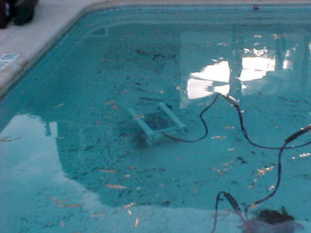
BOB gets ready for a test drive
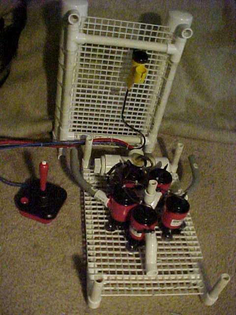
BOB with the top open showing bilge pumps, camera, and electric relay switch housing.
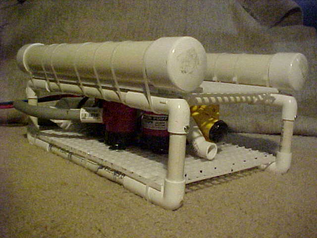
BOB has floats on the top and weights on the bottom pipes that prevent it from rolling.
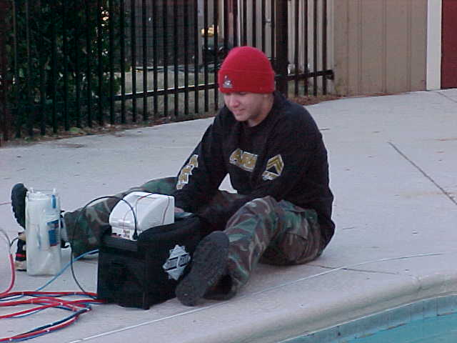
Carl at the controls
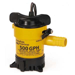
500 gph Mayfair bilge pump
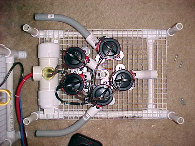
Top view of the 5 bilge pumps. Pipe connected to the pumps directs the thrust.
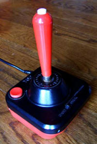
WICO command control joystick
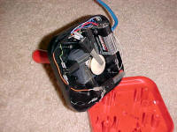
9 Volt battery housed in the base of the joystick powers the relay switches
Leaves on the pool drain!
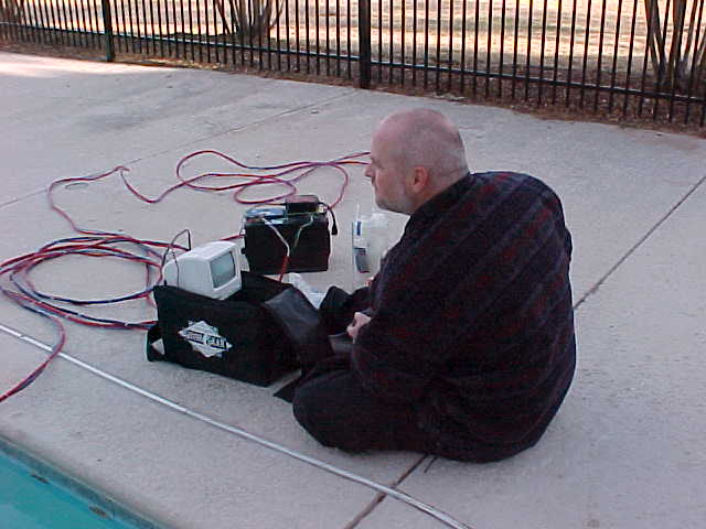
The 12 volt car battery, joystick and video monitor are all connected to the ROV through the umbilical
Pipe insulating foam is attached to the umbilical cable so it floats
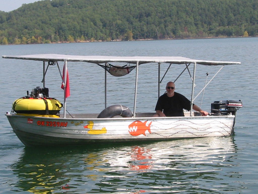
BOB’s boat. The awning shades the ROV’s video screen which helps make it visible. Without shade on a sunny day it is necessary to use a blanket or cardboard to shade the screen from the sun.
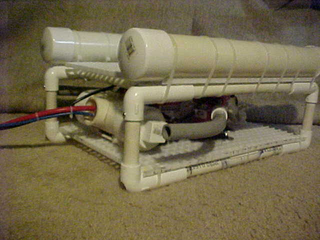
A PVC pipe on the back houses the relays that control the thrusters
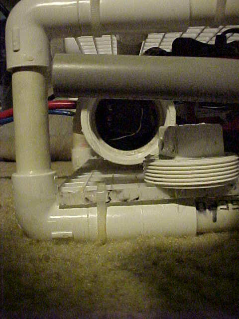
A threaded plug can be removed from the housing and the relays pulled out for repair and replacement

Double Pole Double Throw (DPDT) 12 Volt DC relay.
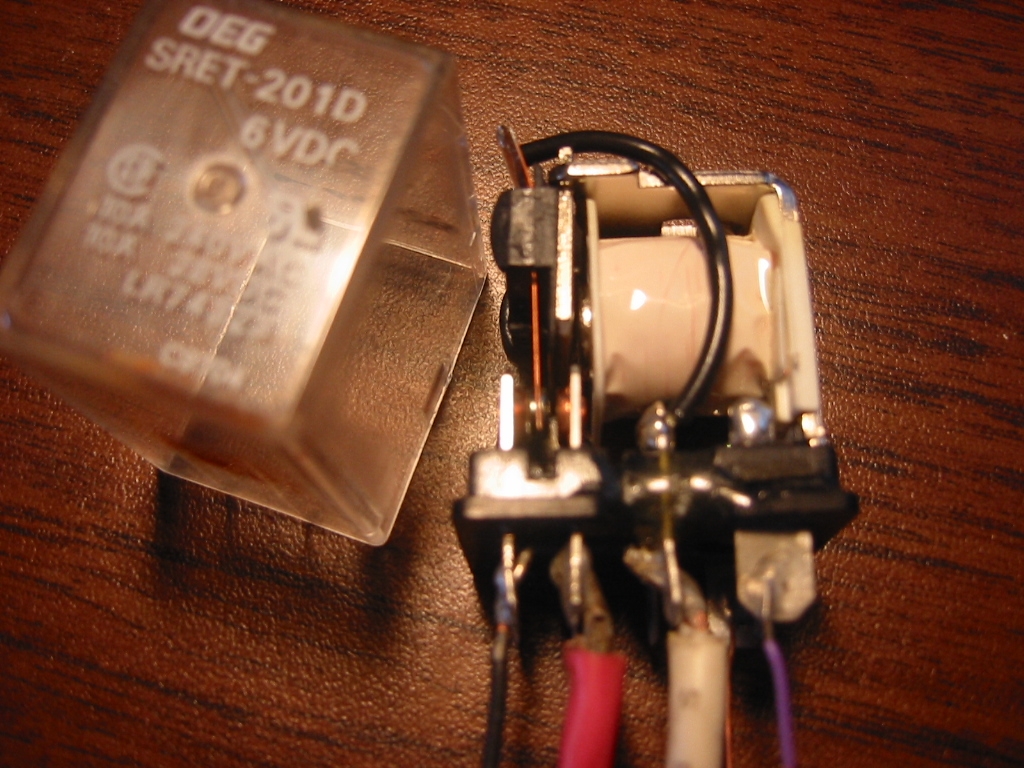
DPDT Relay with the cover removed showing the magnetic coil wrapped in white plastic and the contacts on the left side.
RTV Silicon can be used to seal the wires going into the relay housing to keep the epoxy out
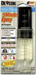
5 Minute epoxy is used to as a strong seal to connect the wire to the relay housing
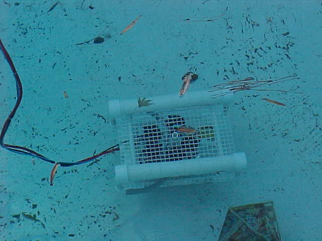
BOB explores the pool bottom on his own
Frame
The frame and floats for Bob are built from PVC pipe, and the grid that the pumps are connected to is cut from a 2 foot by 4 foot florescent ceiling light diffusion panel that is available at most hardware stores. A stolen milk crate works well too, and some shopping carts like those at Target have plastic grids too. Now I am not suggesting you steal anything, but the allies and drainage ditches will often have what you need.
Bob is 19 inches long, about 13 inches wide and 9 inches tall including the floats on top. The floats are 2″ Sch40 PVC and the rest of the frame is 1/2 inch PVC. The float and the grid are connected to the frame with plastic wire ties. Also the camera is connect to the top grid with wire ties and a bunch more will be used for binding the cables together. So when you’re at the hardware store you will want to buy the big can of wire ties.
The bottom PVC pipes running lengthwise or from front to back, hold a 3/8 inch steel bar that is held in place by candle wax so it does not slide around. You can buy 3/8 inch concrete reinforcing bars cut to short lengths at most Home Depot or Lowes hardware stores. You will need a hack saw to cut them to down to length you need. You can also use lead fishing weights or anything else heavy you find laying around for ballast. Making the ROV heavy on the bottom with ballast and light on the top with the floats, keeps it from rolling to the side. The further the floats are from the weighs the more stable your ROV will be. Bob is a very stable with just 9 inches between the weights and the floats, so you can make your ROV smaller without any problems.
The frame is not glued together with PVC glue at most of the joints, but it will make getting to the pumps a lot easier if you use screws on the joints that hold the top grind on. It is best if you first use sand paper to make the pipe that slides into the joint smaller. This will make putting it together and taking it apart easier. Then fit the pipe and fitting together and drill a hole through the joint. You can use a screw or a machine nut and bolt to hold it in place. With the 4 screws removed the top comes right off.
PVC pipe can be bent into curves when it is hot. So you don’t have to have a straight frame if you don’t want one. If you want a special shape or don’t get it glued together perfectly flat, just put it in the oven for about 15 minutes at 250 F. Watch it closely and use oven mitts. When it is sufficiently hot it will bend easily to the shape you want and remain in that shape once it cools for a few minutes. If you are going to make a sharp turn in the pipe, you should first fill the pipe with sand. The sand will keep the pipe from folding together when you bend it.
Thrusters
Bob uses 5 – 500 gallon per hour (gph) Johnson bilge pumps for thrusters. Mayfair makes the same pump. Bilge pumps are normally used to pump water out of the bottom of a boat that has splash or leaked in. Bilge pumps operate off of a 12 volt car battery and cost about $15 each at boating stores like www.wholesalemarine.com. They are also waterproof and have been routinely sent to 65 feet without leaking. The bilge pumps are attached to Bob’s bottom grid using machine nuts and bolts and flat washers.
PVC pipe is connected to the bilge pumps outlet and directs the flow of water to where it is needed. The outlet for the Johnson bilge pumps will fit nicely into a 1/2″ PVC coupler. Looking down on Bob from the top, you can see that two of the bilge pumps are connected to pipes that bend and direct the thrust out the back of the ROV. These two pumps work together to push the ROV forward giving the Bob its’ best performance in forward movement. The thrust from the same two pumps is piped far out to the side which helps when turning. When turning, one pump is off and the other is on. Because the thrust form the pump that is on is out to one side it will push the ROV forward but also make it turn. The pipes used for the forward thrusters are 45 degree bend, 1/2 inch, PVC electrical conduit.
The up and down thrusters each have 2, 45 degree turns to direct their thrust down and up respectively at the center point of the frame. The reverse thruster uses 2, 45 degree turns to lower its thrust to the bottom of the frame. This lets me pitch Bob downward a little with the reverse thruster. This is helpful because the camera can not pitch.
If you have more time than money you can convert bilge pumps to use propellers or you can use DC (direct current) motors with propellers. There are lots of small propellers made for RC boats that can be attached to motors. Using propellers allows each motor to used for both forward and reverse. With most DC motors, switched the positive and negative wires is all that is needed to get the motor to run in reverse. If each motor can produce forward and reverse thrust you can design and ROV with only 3 motors. Motors using props are more efficient the bilge pumps and you can buy much stronger motors for same cost. However, using thrusters that can reverse direction will greatly complicate the ability to use a joystick to control your ROV. If you are up for the challenge then the details are on the “Joystick for Props” page.
Joystick
The joystick you will need is one of the arcade type joysticks that simply has four switches inside. There is one switch for each direction that the handle can move. You will want two other buttons as well. One of these buttons will be for down thrust and the other for up. You can find these joysticks for about $10 on ebay or from arcade game part suppliers. I used an old Wico Command Control joystick that was used on Atari games back in the 1980’s.
The base of the Wico joystick actually has enough room for a 9-volt battery that is used to control the bilge pumps. And it has two buttons for controlling up and down. One is on the top of the handle and the other is on the base. It also has a off-on slide switch on the base that can be wired to disconnect the 9-volt battery so the pumps don’t accidentally get switched on and drain the battery.
Camera
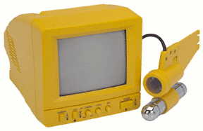
The camera and monitor I used is an Atlantis™ Guide View Underwater Camera System the cost $250 but you can now get similar units from www.harborfreight.com for around $110. Both of these ready to use video systems come with a black and white, waterproof video camera and 65 feet of thin coax cable that connects to a small 12 volt video monitor and 12 volt battery that provides power for the camera. There are inferred LED lights on the camera that surround the lens, so it is possible to use the camera in complete darkness.
If money is tight you can pick up a used video camera and portable TV. You can build a simple water tight camera housing from PVC pipe fitted with a clear acrylic view port.
Having the LED lights so close to the camera lens is actually a bad design because it causes “back scatter”. When small partials in the water float up close the the camera lens they are also close to the LED lights so the are very bright and that blurs out the rest of the picture. If you do build your own camera housing, consider using a camera with no lights around the lens and instead use a separate light mounted off to the side and above the camera. The lights should also not be in the field of view of the camera.
You can also find waterproof color cameras. It is often easier to identify something from its color, but black and white cameras are actually better at showing outline and shape of objects.
If you have a choice among waterproof cameras or if you are going to build your own camera housing and can select your camera, then try to find a camera that works well in low light, or a low Lux camera. But be careful one manufacturer may list their .001 Lux while a another manufacturer with a better camera will list it as .1 Lux. The problem while the .001 camera may work in very low light, the quality of the image may be very poor. It is left up to the manufacturer to decide what Lux number to assign.
Umbilical
The umbilical or tether is the bundle of cables that connect the ROV back the the surface. For Bob that is three cables. One provides power to the pumps from a car battery. One connects the joystick to the relay switches, and one connect the video camera to the video monitor.
People building ROV’s sometimes try to make there ROV faster by making it more streamlined; like a racing car. If the water flows around the ROV smoothly then the ROV will be faster, but only until it starts to drag the umbilical along behind it. If you plan to use your ROV a river on in the ocean where there are currents it is very important that you do everything you can to make the umbilical as thin as possible. For example, the power cable in Bob’s umbilical is a 12 awg extension cord. If Bob was going to work in the ocean it would be better to have just two 12 awg wires and wrap them tightly with electric tape to the video and computer cable. A stream lined ROV is not important for lakes. Bob moves fast enough that things often pass by faster that you can tell what they are on the video monitor.
Bob’s three cables in the umbilical are bound together with plastic wire ties every 10 inches or so. One foot pieces of foam pipe insulation are wrapped around the cable at 6 to 8 foot intervals again using plastic wire ties. The wire ties holding the cables together prevent the foam from slipping along the cable. The first float is about 5 feet from where the cable attaches to Bob. With the each float piece in place you feed umbilical into the water until the piece of float just attached was almost ready to sink, and that is where you add another float. At the lake in deep water is the best place to add the floats. You can put a some temporary weights on the ROV to make it slightly negative buoyant so it would gently pull the floats down. This is best approach because the insulation is soft and easily compresses the deeper your ROV goes. When the ROV is at 40 feet the float nearest the ROV will have compressed and lost some of it’s buoyancy, so the float on the surface 40 feet above had to be a little longer or little closer to the previous float. When you latter stretch out the umbilical you will see that the floats further away from the ROV are noticeably closer together.
Once you’re done adding the floats, you will want to remove the extra weights from the ROV. It’s best to have the ROV slightly positive buoyant. Two reasons for this. First, it will return to the surface on it’s own if you loose power instead of falling to the bottom where it might get snagged on a log. And second, when you are just over a muddy bottom you will be using the down thruster to stay close to the bottom, instead of the up thruster that will immediately stir up the mud so that you can’t see anything.
You can store the umbilical on a spool, but it is easiest if you just pile it into the bottom of the boat. This lets you keep the cables all connected.
Wiring
You will need a soldering iron, some flux, and solder, but the soldering is not delicate work so it is a good project for a beginner.
Most of the soldering is done to make the connections on the relay switches are housed down on the ROV. The housing for the relays is a 2″ PVC pipe mounted on the back of Bob and it must be waterproof because the relays will not work if they get wet. The power wires from the battery, computer cable from the joystick, and all of the wires from the pumps enter the housing thought one or two holes that are later sealed with epoxy. There is a threaded plug on the relay switch housing that let you remove, inspect and replace a relay if needed.
Below is a wiring diagram for Bob. The joystick is wired so that pushing forward on the stick turns on both the left and right forward thrusters. Left and right turns are made by using only the left or right thruster, so pulling right on the stick runs the left forward thruster. Pulling back on the joystick engages the single reverse thruster that is mounted in the center. Pulling back and to the right turns on the reverse and left forward thruster giving a nice tight right turn.
The small wires in the computer network cable connect the switches in the joystick to the relay. When the joystick is moved to the right, you want the left side pump to turn on. So, when the joystick is moved to the right, a switch in the base of joystick is closed and power from the 9 volt battery flow down a wire in the computer network cable to the relay for the left bilge pump on the ROV. The power from the 9 volt battery flows throw a coil in the relay and creates a magnetic field. The magnetic field then causes the switch inside the relay to flip, and power from the 12 volt car battery then flows to the left bilge pump that pushes forward on the left side making the ROV turn to the right.
So why not just wire the car battery and the bilge pump directly to the joystick? First, most joysticks do not have switches that will handle the power required by the pump. Second, you would have to use a seperate12 awg wire from the joystick to the ROV for each pump and that would make the umbilical much larger.
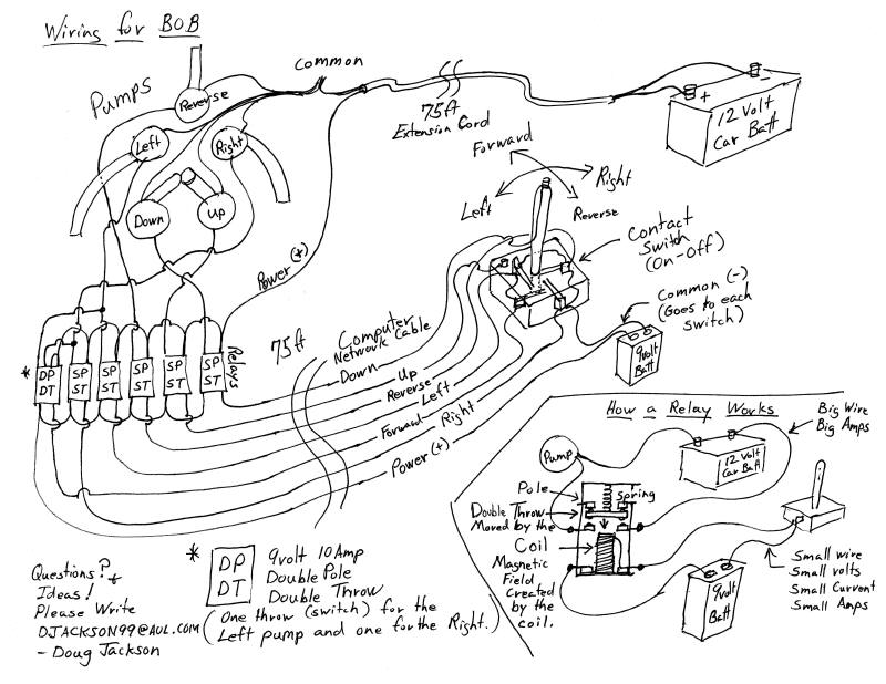
There are some things you need to pay close attention to when selecting your relays. All relays have a coil that needs a small amount of power so that it becomes a magnet strong enough to close the switch contacts, and all relays have the switch or contacts that close and connect the larger power source to the load. In this case the car battery is connected to the bilge pumps. You need a relay that has a coil that will close the contacts with less than 9 volts, and the contacts should be able to carry more amps that what your pumps need.
For example www.allelectronics.com list a relay as “5VDC SPDT 6A RELAY” and the detail is: “Hasco # KLT1C6DC5. 5Vdc, 70 Ohm coil. S.P.D.T., 6 Amp contacts.” The coil on this relay works with only 5 volts DC because the the resistance in the coil is only 70 ohms. That is well below the 9 volts you are going to send to the coil so it should close easily. You will sometimes just see the resistance or ohms listed for the coil. If that is the case then find one that is 70 ohms or less. The contacts on this relay are 6A or 6 amps. The 500 gph, bilge pumps use about 2 amps so 6 amps is more than enough. This relay is a SPDT so it will work fine as a SPST if you just ignore the extra connection. You would still need one, DPDT relay, and you could use two of the above SPDT relays or shop around for a DPDT. Not that the DPDT relay powers two bilge pumps so you might think that it’s contacts need to be rated with more amps that what two pumps would use, but in reality the two pumps use separate contacts in the relay so matching the relay amps to the pumps amps is fine to do.
Once you have soldiered and tested everything, then you are ready to waterproof the relay housing with epoxy. The first step is to seal the wire where they enter the relay housing in order to keep the epoxy out. You can get RTV Silicone from any auto parts store and the fast dry RTV will be ready less than one hour if you are careful not to use too much. You can then follow the diagram below to make a form for the epoxy or you can get modeling clay from the craft store and make a form around the wires with clay.
For more information on ROV’s I recommend Steve Thone’s Homebuilt ROV’s page: www.homebuiltrovs.com Steve has multiple ROV’s and he maintains a good link page to other home made ROV’s.
Best of luck to you. If you need any questions answered, I will try to help. You can write me at svseeker@ymail.com. I also recommend the Yahoo Robotrov forum or the Yahoo International Psubs Minisubs ROVs forum.

