|
|
|||||||||||||||||||||||||||||||||||||||||||||
Gantry and Hoist
Disclaimer: If you build something yourself or if you modify a manufactures product in any way the you are assuming all of the consequences for your actions. If it breaks and drops an engine on your pregnant wife it is your fault. If you believe anything else then stop reading and go to some other web site. Until I had some way of suspending engines, steel or entire boats in the air it is hard to realize how much easier it would make my work. So when we decided to build a large sailboat I was planning on a the crane or gantry long before we knew exactly what we were going to build.
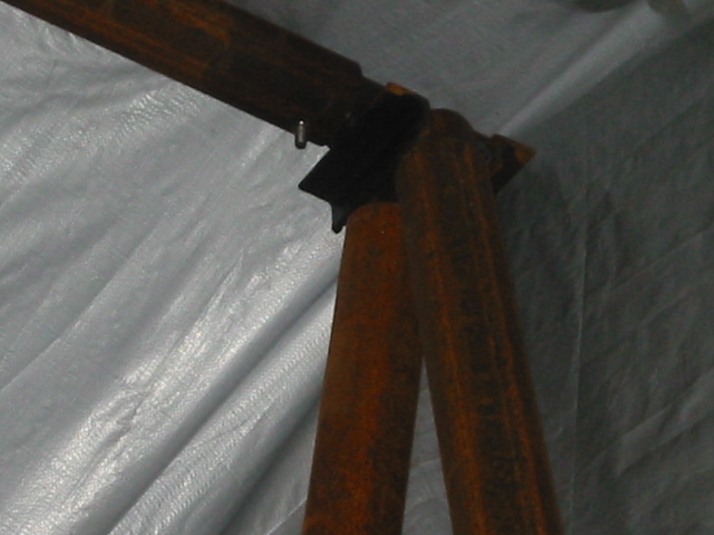
A-FrameI started with an 8 foot span A-frame from 1/4 inch thick, 2 1/2 inch ID steel pipe and it is great for lifting the sub or the engine but it's a little over stressed to do both or about 1 ton, and it would never be able to handle the sub with it's ballast sled in place which would total 2 tons. The wheels on the A-Frame are good for 300 pounds each and available from Harbor Freight for $9 (2008) each. None of these pivot so turns require dragging a wheel sideways but it is much better that walking the A-Frame around by moving one leg at a time. The A-Frame is held together at the corners with a bracket
made from 3 pieces of 16 inch long 2 1/2 inch OD pipe and a bit of
angle for reinforcement. This lets the legs and cross piece
just slip onto the bracket and only 1 bolt is used the secure the
cross piece so it does not slide out. Each leg weighs about 60
pounds, so standing the thing up is a bit of a task requiring a
couple of strong friends or some 2x4 bracing. The steel in 2005 cost
$75 from the scrap yard and Harbor Freight had their 3 Ton chain
hoist on sell for $65 dollars.
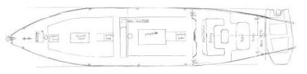
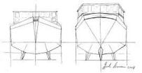
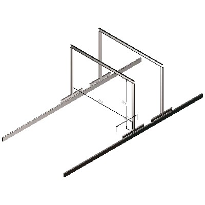
GantryPlans(1) We chose dual gantries because the sailboat will be about 70
feet long and built using the origami method that requires handling
a 13 by 75 ft sheet of metal. Having two lifting point will
make that a much easier task. Both gantries will be supported by
grooved wheels that roll alone a 1 inch steel angle on top of
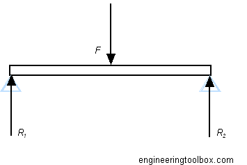
concrete beams in the ground. (2) I found the following resources on www.engineeringtoolbox.com. The "Stresses and Deflections in Beams" page has a calculator specifically for "Beam Supported at Both Ends, Load at Center". The other page, "American Wide Flange Beams" list all of the standard wide flange beams and their corresponding "Moment of Inertia" number that is entered into the calculator. Stresses and Deflections in Beams American Wide Flange Beams
Below are the results: Total Load :
10000 (lb) --5 Tons A 1/400 ratio is normal deflection for
living space which would be about 3/4 inch for 28 ft, however that
is just because people don't like floors that bounce. In this case
1 3/4" is acceptable but there is no room for safety. Steel
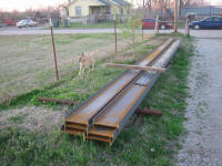
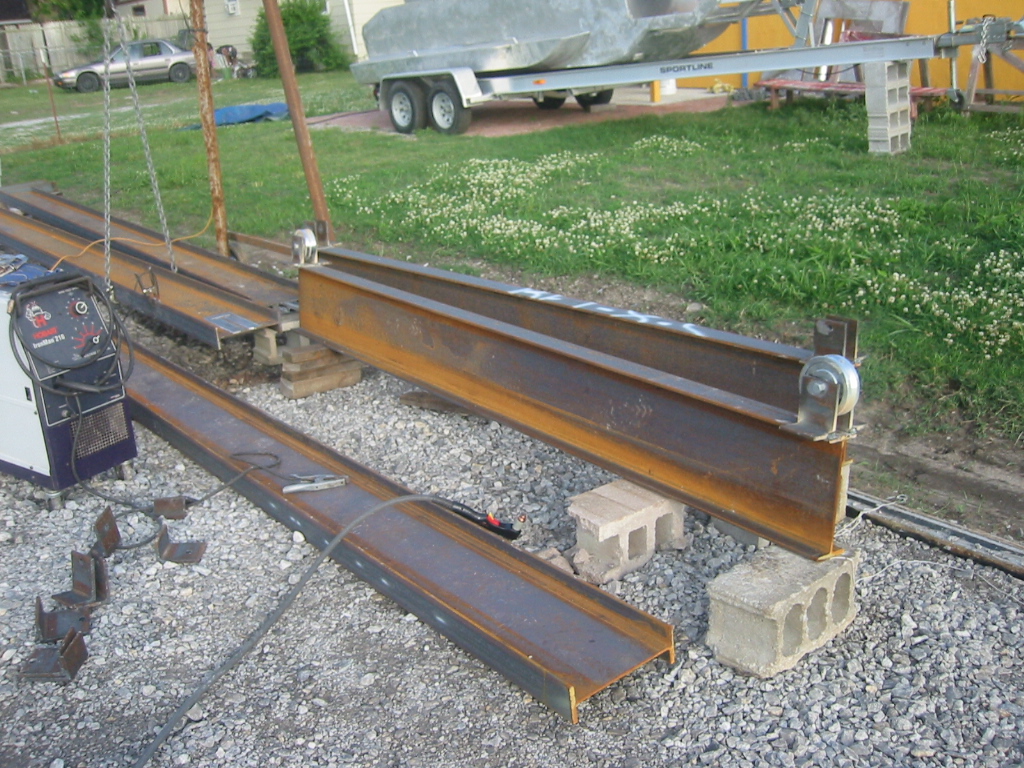
The 6 - 30 ft, W12x22 I-beams will come from Interstate Steel. Their back gate is literally across the street from our house so there fork lift can deliver it right to my front yard. The cost per foot for a W12x22 I-beam is $13.20/ft or a total of $2,376. Steel prices are going up every day. Last week is was .53 cents a pound and this week it's .58 cents a pound, so I purchased the steel as soon as I knew what I needed. I'd complain about the Chinese buying all of the steel, but I just ordered a bunch of chain fall hoist, trolly's, leaver chain hoist, and an electric hoist at prices that are hard to believe considering the number of pounds of steel in the order. I just wish they would bring the quality up a little. I always think about those dirt foundries that Mao had the Chinese farmers setup when I working in the sub and that diesel engine is suspended above me on a Chinese hoist with Chinese chain. Hopefully they are not using the same foundries.
|
|||||||||||||||||||||||||||||||||||||||||||||
|
||||
Kay and I are grandparents now, and grandma is out with baby Aden and mom while dad is off playing war games with the British Army in Germany. So progress has been slow lately but I have managed to get some work done.
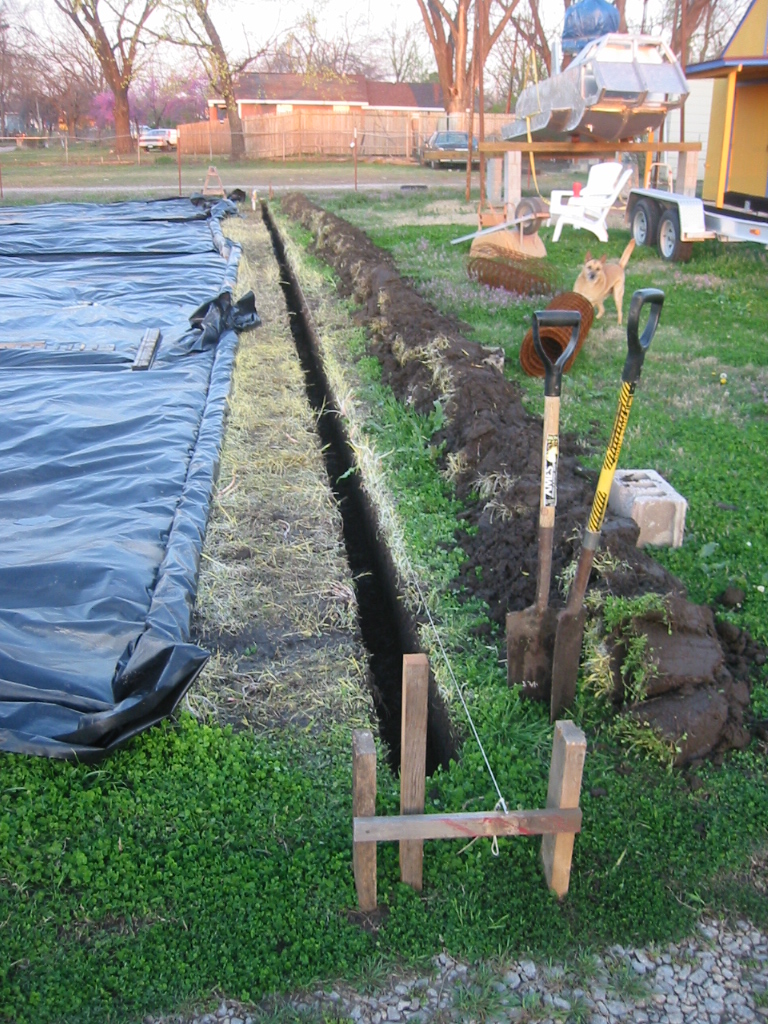
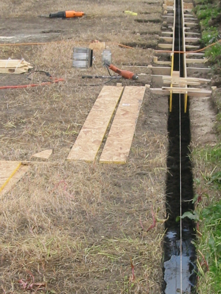
(1) (2) In between April thunder storms, I dug two parallel trenches, each about 6 inches wide and 14 to 16 inches deep. It took longer to set the forms that are 4 inches wide. Both beams are level with each other but both also slope 1 inch for every 10 feet. This keeps to the natural slope of the yard and will help with drainage. I'll just set one wheel on the gantry an inch lower that the other to match the slope.
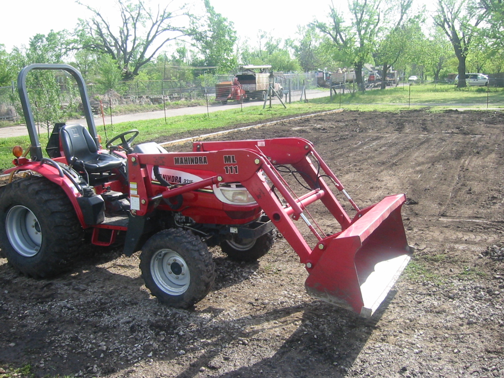
(3) I rented a small 4-wheel drive tractor with a box blade and managed to level the site, leaving 3 to 4 inches for rock to go in between I rented a small 4-wheel drive tractor with a box blade and front end loader and managed to level the site. I left room for 3 to 4 inches of rock to go in between the concrete beams. I will cover it back with plastic and then have the rock tucked in after a week or so just to give it time to dry out so the truck does not get suck.
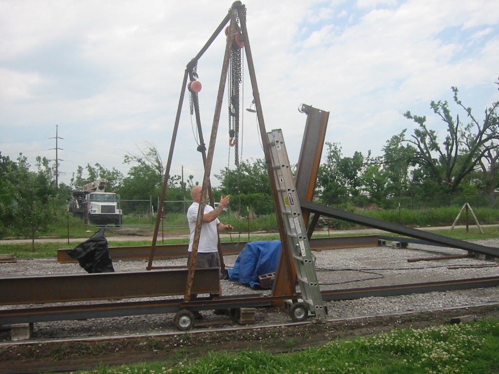
Assembly
|
||||||
With only a 12 foot high A-frame to work with, the two gantries were assembled on their side.
(1) The V-groove wheels support 3 tons each and came from www.acecasters.com for $40 each, so a total of $340 for all 8 with shipping in 2008. The foundation slopes at 1 inch for every 10 feet and the base of each gantry is 10 feet long, so the wheels on the down hill end are 1 inch further from the base beam.
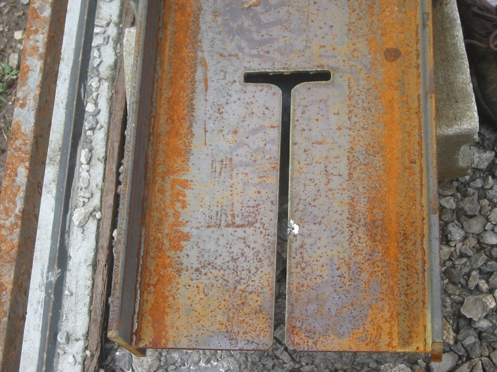
(1) (2) A jig cut from aluminum guided the plasma torch to cut a slot the bottom end of the vertical beams. With the 20 foot vertical beam laying on its side, the bottom beam was hoisted vertical on the A-frame and set into the slot.
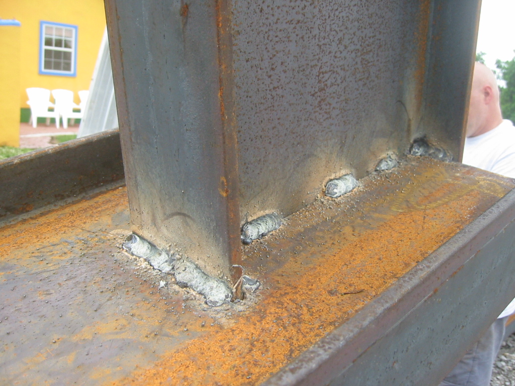
(3) (4) (5) A second hoist then raised the end of the vertical beam 5 feet up so it could be welded to the bottom beam.
Kay was busy cleaning and painting while as ladder would not be needed. We found paint for only $6 a gallon on www.craigslist.org from a guy who collects incorrectly mixed paint from Sherwin William Paint stores.
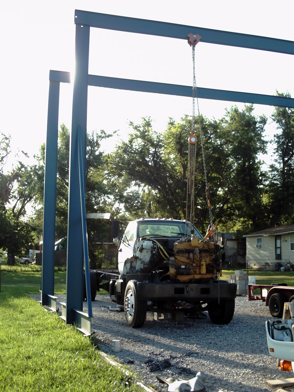
Erecting the Gantries
|
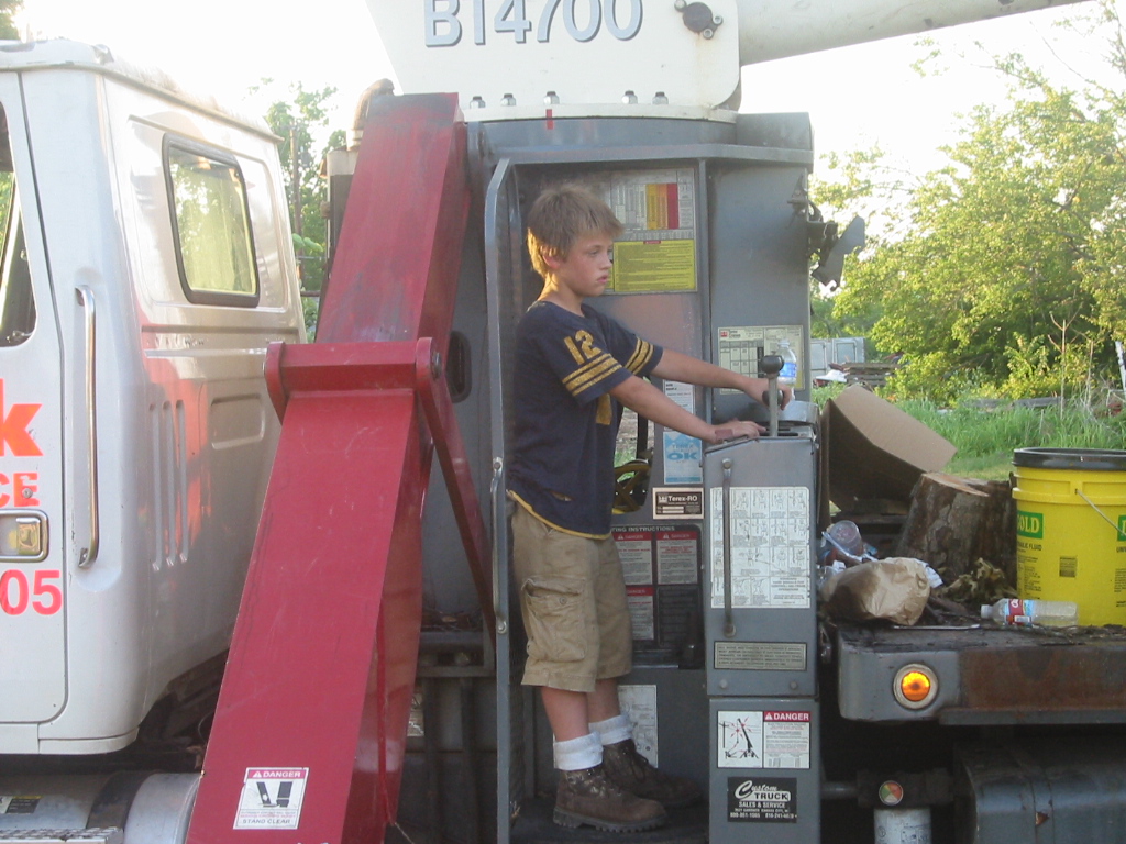
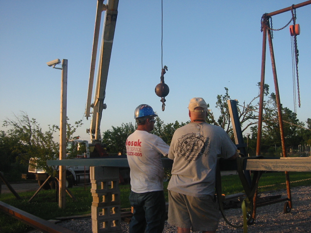
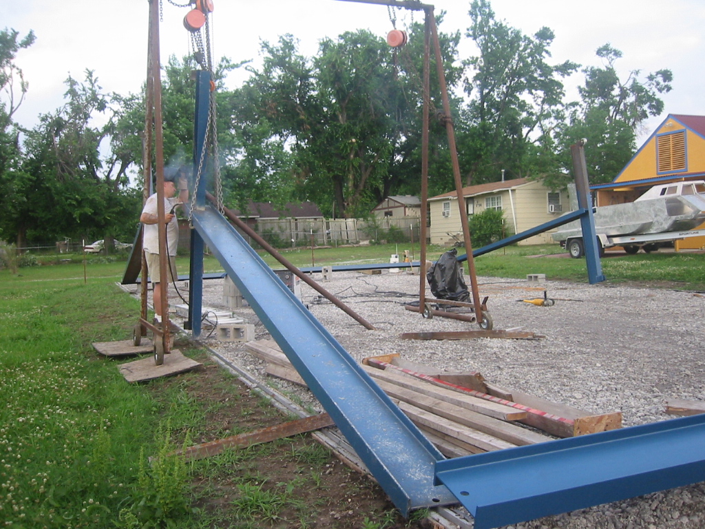
Standing the gantries up was a piece of cake. But my neighbor is "Nosack Tree Service", and Paul Nosack and Calib his 11 son pitched in to lift the gantries. It's a real hoot having Paul's business across the street because Paul has his own reality cable TV show. See www.nosackraw.com
Plan "B", if Paul was too busy or if his
crane was out-of-town, was to stand the gantries up without a crane.
I had already purchased a 30 foot long 6 inch I-beam that would
become the spreader. The plan was to lift that I-beam with the
A-frame and stand it almost vertical. Then secure it to the
A-frame, secure a steel cable pulley to the top, and another to the
bottom. The steel cable would run from the cross member on the
gantry thought the top pulley, down to the bottom pulley and then to
winch and dead-man a safe distance away. It would have been
fun to try, but much more risky than the crane.
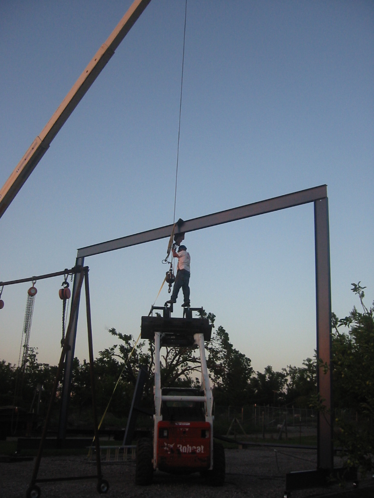
(1) This was Calib's first time to lift a load with the crane and he
did a great job, without too much yelling from Paul. I can't think
of a better way to educate a child than to give them real
responsibility.
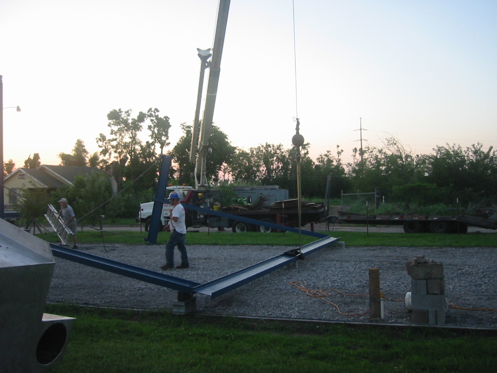
(2) Steel I-beams easily twist, so to keep the vertical beam from twisting while the weight was on the ends of the bottom beams, I ran chains between the wheels on the bottom beams to form a large X.
(3) Then we just stood around and let Calib to maneuver the hook into place.
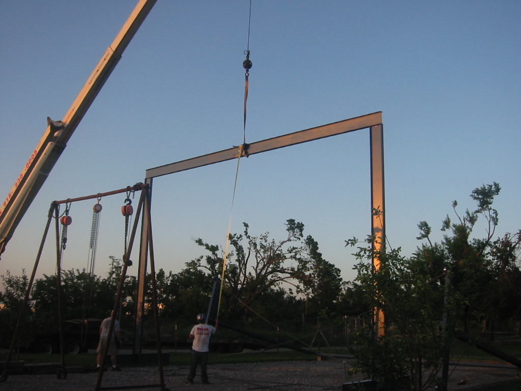
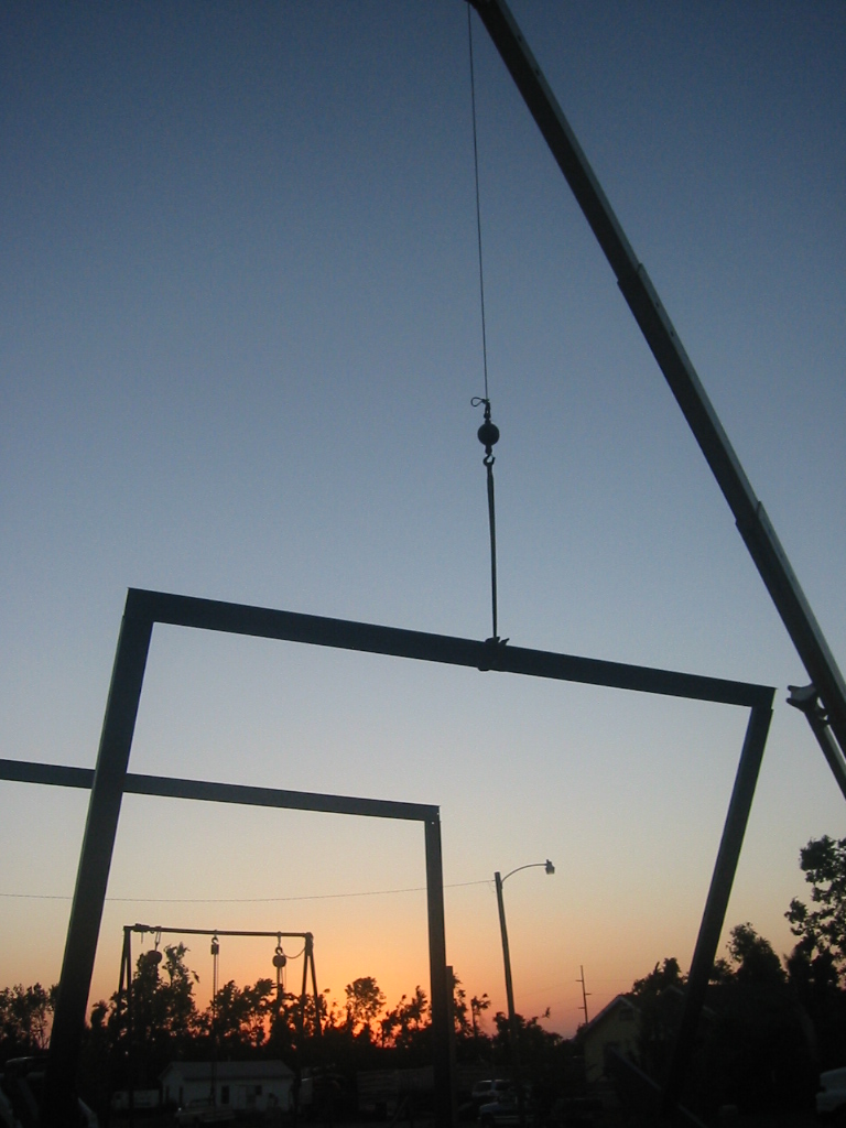
(4) (5) The gantry whet up without a
hitch, but I did not have a 28 foot ladder yet so Paul rode the
Bobcat's bucket up to disconnect the hook. (6) As the sun when down
the second gantry went up.
Final Assembly
|
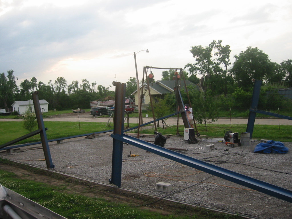
As suspected there was too much sideway flex in the vertical beams. Most of this was because they were connect to the bottom beams only using their webbing and not their flanges. The problem was anticipated and easily corrected. Since the A-frame was no longer needed is was disassembled and the legs became braces between the ends of the bottom beam to a point in the vertical flange 12 feet up.
We were surprised at how easily the gantries can be rolled. It is best done with two people, especially in the up hill direction, but it only requires a firm push to get it moving. In fact is was so easy that we wrapped chain around the wheels to chalk them. Even then we had a bit of excitement the first night when a thunder storm blew in. Kay and I when out front to see how much the gantries would flex in the wind, and when the wind kicked up to about 20 mph, one them gantries started rolling away pushing the chain we used for chalks. Luckily it jumped one wheel off the the track and came to a stop before it reached the end of the rail and the ditch.
With a a little searching on the web about
signs, I learned that a 70 mph wind puts a 22 pound per square foot
load on a flat surface. The gantries have 30 sq ft in the top beam
alone, and that is on the end vertical beams that act like a 20 foot
leaver. I figure a 45 mph wind could likely blow the gantries
over. To head that problem off we added dead men with chains
that can be locked into the bottom beams.
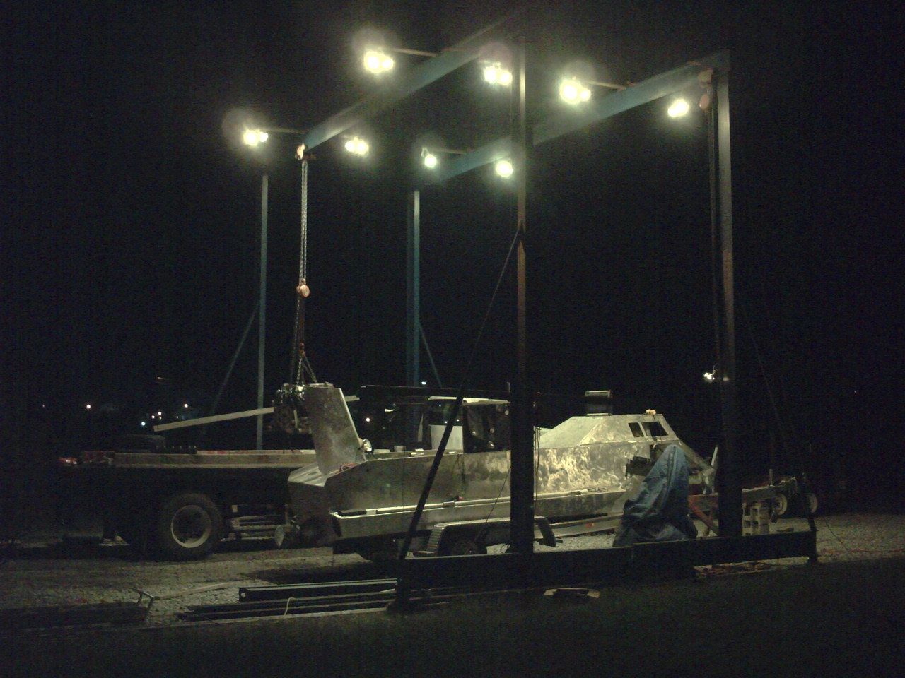
Latter we added lights, and they are wonderful. No more moving
a clip on light around or bugs flying up your nose. These are
just flood lamps screwed to 2x4's that are clamped onto the top of
the cross beam using lag screws and large washers.
Gantries Finally Get Used as Intended
Flipping over her 5 ton half hull, and a bit of excitement.
...and with Electric Winches!
Flipping again but this time with Budgit electric hoist and not the Harbor Freight manual chain hoist. ...what a difference $6,400 makes. Yes. They cost $3,138.76 each.
But buy extra fuses. These use 300v 1/2 amp glass fuses. When a weld broke while lifting a 600 pound plate the winch responded by blowing a fuse.
DIY Vertical Plate Clamps
Hoist
I purchased 4 very cheap Chinese chain hoist from CVF Supply, http://cvfsupplyco-store.stores.yahoo.net/ for $90 each. They only came with only 10 feet of chain fall so I had already planned switch the chain but that is not easy to do. After talking with a few chain suppliers I learned that there is not a very good standard for chain sizes and the Chinese are bad about following what standards there are. Oddly enough I measured the chain I used for turning my hoist and found it on a few sites but then learned that the numbers listed on the web may not be what they will ship to you since each manufacture's chain is slightly different and they don't bother checking it against what they advertise. I didn't bother asking why they had numbers on their sites that they knew would might be wrong.
Chain is loosely grouped into grades for strength and approximate size. I wanted galvanize chain to replace the short 3/8 inch chain that came on my Chinese chain hoist so I found some grade 43, 3/8 inch hot dipped galvanized chain that was load rated at 5400 pounds. The link size was the close but not close enough.
|
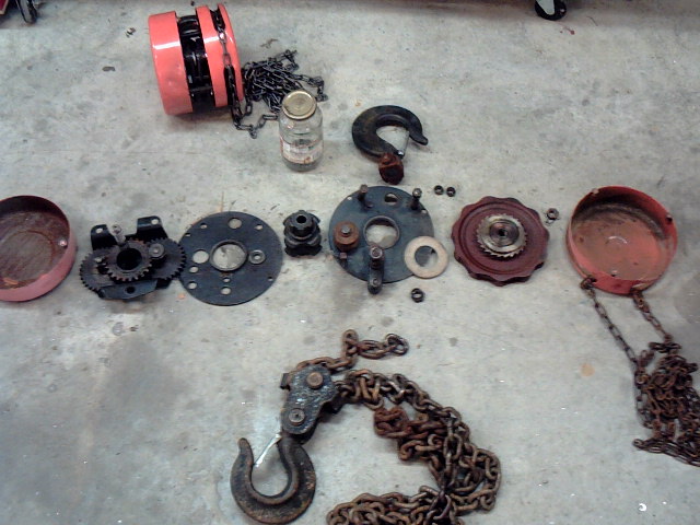
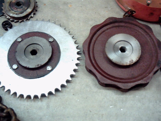
(1) Unfortunately the 3/8 inch chain I got was just a little too big so I disassembled the hoist and added some weld to the main sprocket to make it big enough for the new chain. I had the same problem with the smaller chain used to raise and lower the main block.
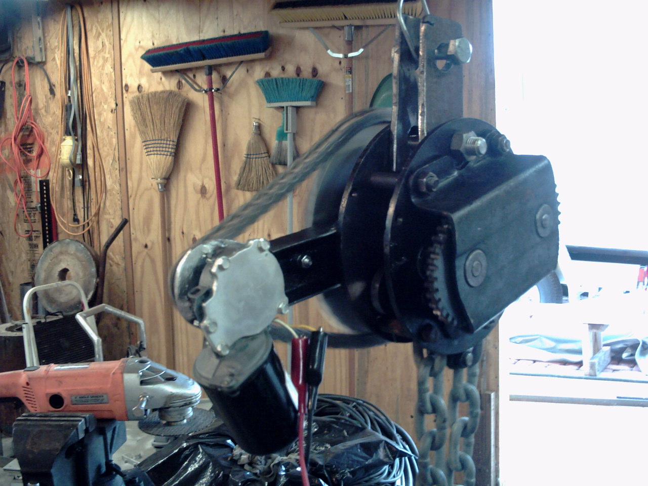
(2) While I had the hoist apart I had a rather hastily thought out idea of replacing the chain pulley with a sprocket and the powering the hoist with a 12 volt windshield wiper motor. I already had the cast aluminum sprockets leftover from a previous experiment so I cut away the rim of the chain pulley and bolted on the aluminum sprocket.
(3) (4) The windshield wiper motor uses a worm gear and with the
reduction on the chain sprockets it had no trouble turning the chain
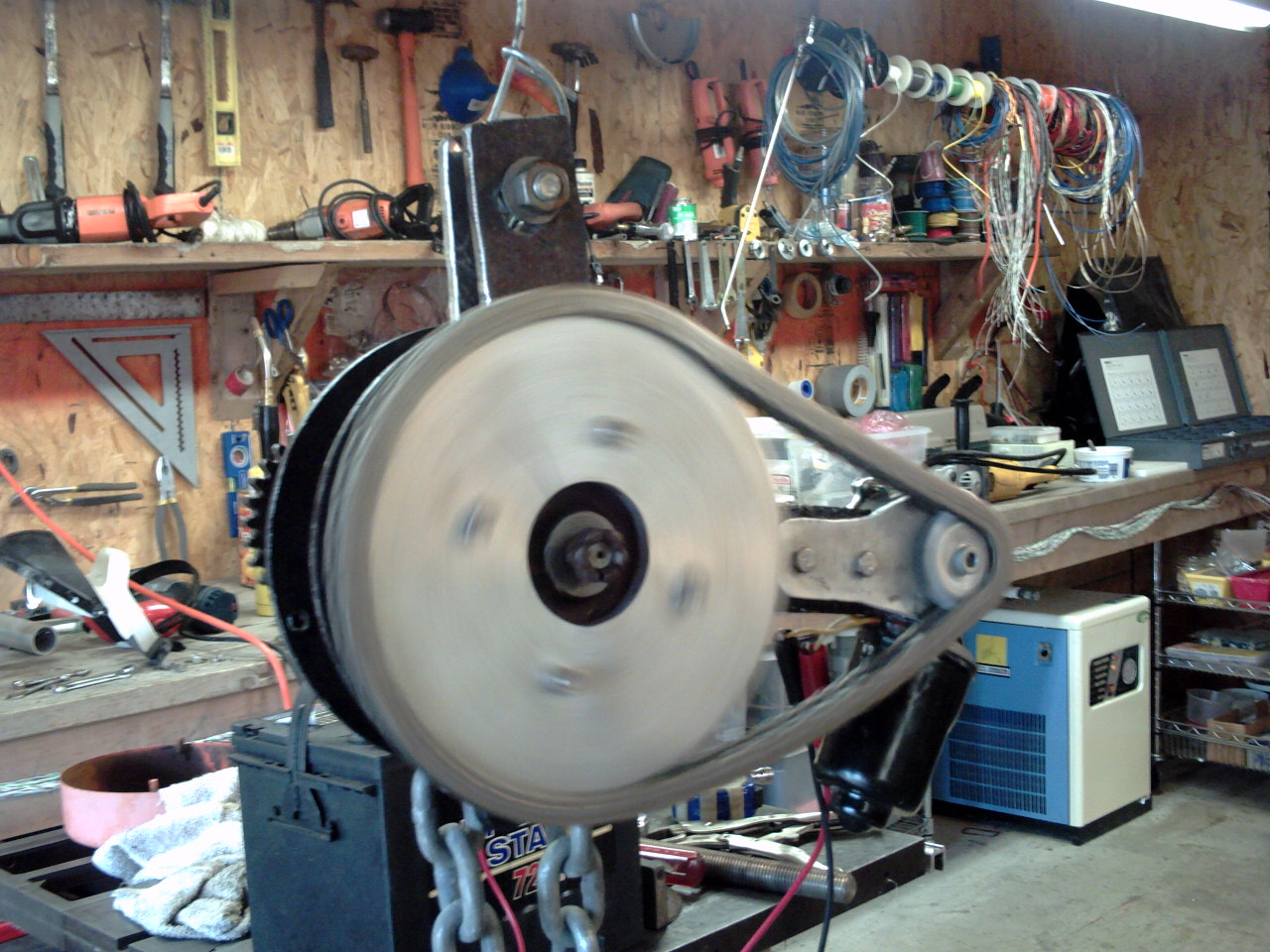
hoist. But what I did not calculate ahead of time was the
speed. The wiper motor is only 80 rpm, the reduction from the
sprockets brings it down to about 16 rpm, and while the chain moves,
that is just way too slow. A bigger motor would solve the
problem, but I didn't have any laying around so I welded the
original rim back on.