 Seeker Knowledge
Disclaimer: If you build something yourself or if you modify a manufacturer’s product in any way the you are assuming all of the consequences for your actions. If it breaks and drops an engine on your pregnant wife it is your fault. If you believe anything else then stop reading and go to some other web site.
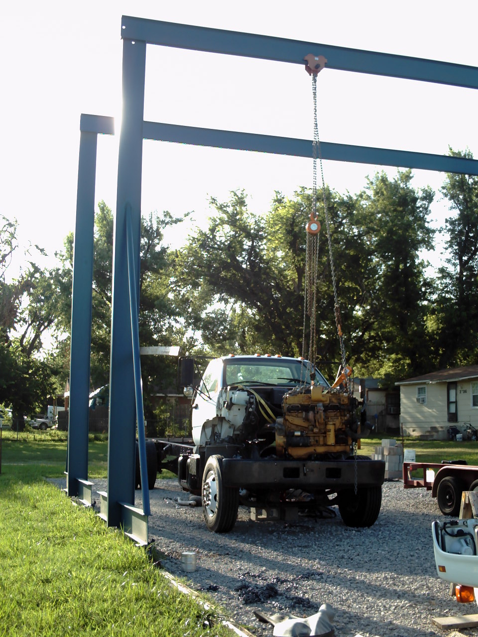
Until I had some way of suspending engines, steel or entire boats in the air it is hard to realize how much easier it would make my work. So when we decided to build a large sailboat I was planning on a the crane or gantry long before we knew exactly what we were going to build.
A-Frame
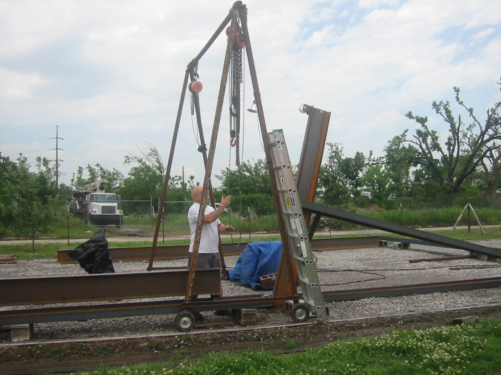
A-Frame erecting the gantry.
I started with an 8 foot span A-frame from 1/4 inch thick, 2 1/2 inch ID steel pipe and it is great for lifting the sub or the engine but it’s a little over stressed to do both or about 1 ton, and it would never be able to handle the sub with it’s ballast sled in place which would total 2 tons.
The wheels on the A-Frame are good for 300 pounds each and available from Harbor Freight for $9 (2008) each. None of these pivot so turns require dragging a wheel sideways but it is much better that walking the A-Frame around by moving one leg at a time.
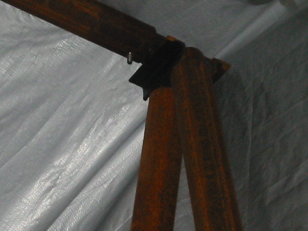
Top bracket on the A-Frame.
The A-Frame is held together at the corners with a bracket made from 3 pieces of 16 inch long 2 1/2 inch OD pipe and a bit of angle for reinforcement. This lets the legs and cross piece just slip onto the bracket and only 1 bolt is used the secure the cross piece so it does not slide out. Each leg weighs about 60 pounds, so standing the thing up is a bit of a task requiring a couple of strong friends or some 2×4 bracing. The steel in 2005 cost $75 from the scrap yard and Harbor Freight had their 3 Ton chain hoist on sell for $65 dollars.
Gantry
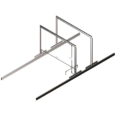
(1) Dual gantries, 20 foot tall with a 30 foot span, rolling on 70 foot concrete foundations.
(1) We chose dual gantries because the sailboat will be about 70 feet long and built using the origami method that requires handling a 13 by 75 ft sheet of metal. Having two lifting point will make that a much easier task. Both gantries will be supported by grooved wheels that roll alone a 1 inch steel angle on top of concrete beams in the ground.
There are several online calculators for floor beams but you need to use a calculator is for center loaded beams without an lateral support that would come from having the beam connected to a floor or ceiling.
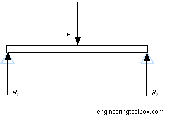
(2) I found the following resources on . The “Stresses and Deflections in Beams” page has a calculator specifically for “Beam Supported at Both Ends, Load at Center”. The other page, “American Wide Flange Beams” list all of the standard wide flange beams and their corresponding “Moment of Inertia” number that is entered into the calculator. www.engineeringtoolbox.com
(2) End supported, center loaded I-beam calculator from www.engineeringtoolbox.com
Stresses and Deflections in Beams www.engineeringtoolbox.com/beam-stress-deflection-d_1312.html
American Wide Flange Beams www.engineeringtoolbox.com/american-wide-flange-steel-beams-d_1319.html
Using the above calculator for my gantry I entered 5 tons for the load and 28 ft for the length and then the Moment of Inertia for various I-beams watching the resulting Maximum Deflection until I settled on a W12x22 beam. The W stands for Wide flange, 12 is the web height in inches, and 22 is the pounds per foot.
Below are the results:
Total Load : 10000 (lb) –5 Tons Length of Beam – L : 336 (in) — 28 ft open span. The beam is actually 30 feet long. Moment of Inertia – I : 156 (in4) –This comes from the list of standard wide flange I-beams Modulus of Elasticity – E : 29000000 (psi) Perp. distance from neutral axis – y : 6.25 (in) Support Force – R1 : 5000 (lb) Support Force – R2 : 5000 (lb) Maximum Stress – s : 33654 (psi) Maximum Deflection – d : 1.75 (in)
A 1/400 ratio is normal deflection for living space which would be about 3/4 inch for 28 ft, however that is just because people don’t like floors that bounce. In this case 1 3/4″ is acceptable but there is no room for safety.